mlucitt
Veteran and General Yakker
I have heard it called Wakefield Compound, zinc oxide, silicone paste, or Dow Corning 340. Others use plain mica or Silipads. What do you use and why???
Lee, I am too dumb to find the "Archives" so I am taking an action item: I will ask Joe to include the information on the sil-pads he uses on his next BOM update. In the meantime, he was gracious enough to offer me (16) of the little buggers for a fair price along with the (16) new MJ output transistors he is sending me for the PL400. It will soon be singing a different (WOAPL) tune...In the Archives there should be a part number in the "parts" thread...
So NO thermal grease along with the sil-pads?Sil-pads...better heat conduction.....oh....and less mess. Get the gray ones that look like they are embossed...
So NO thermal grease along with the sil-pads?
Oh, I was lookin' for something different. Thanks Fred!Fred got it Mark...


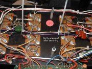
What is the consensus of the group on these capacitors on the PL400 transistor wall? They are not shown in the schematics I have. My early PL400 (serial #2225) does not have them, so I don't know the values. Are they like the ferrite beads in the PL400 Series II, an undocumented factory modification? Do they help with EMI or blocking AC? Thanks to Don for use of this picture.
View attachment 35612
