https://www.ebay.com/itm/Vintage-Ph...218505?hash=item3fc122bb49:g:S00AAOSwSv9cw4BC
Does anyone know who this person is that is selling this amp?
Just in case the ad disappears I have copied the text and pasted it below:
Up for auction is a PhaseLinear 400 series I rated at 200 watts per channel into 8 ohms.
I acquired these twoPhase Linear amplifiers from a seller who did not have the ability to restorethem.
Please note that there are TWO (2) auctions for these Phase Linear amplifiers and I am using common text and common pictures in BOTH auctions owing to the fact that I performed the exact same work on BOTH amplifiers and they look identical.
Below is what I did to restore the two amplifiers:
Stripped both amplifiers completely and sent all the aluminium panels to be re anodized.
The front panels were very bad and so I discarded them and had some new ones made.
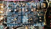
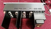
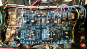
I designed a new double sided printed circuit card which houses the two channel’s drive circuits and the DC protect relays. The same relay control drives the surge protector relay. This is required because of the new rail capacitors which are now 27,000mfd 100v low ESR types rated to 105C. The original rail capacitors were either 5600mfd or 5900mfd 85v.
The transformers in both of these amplifiers had their secondary voltage higher than what Phase Linear claims in their service manual. Depending on the vintage, the railvoltage was either +/-75v, +/-80v or as in the case of these two +/-85v. I have no problem with the higher rail voltage as I used 100v capacitors and the amplifiers delivered slightly more power.
The power supply originally stored 42 joules per rail. Now it stores 195 joules per rail!
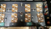
The heat sinks accommodate 8 TO3 power transistors per channel where two of these are drivers leaving an output stage with only 3+3 output devices. Even with the new output transistors the output stages were marginal if 4 ohm loads would be driven.
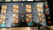
So I made the positions, where the driver transistors were, into an extra pair of output devices and added in a pair of high speed TO3P Toshiba 15 amp driver transistors in order to keep the output triples. These can be seen in thepicture.
There was never anydoubt that the original PL909 output transistors would not be used as they were totally unreliable parts.
I used MJ15003/MJ15004 transistors and converted the output stage to a full complementary design with active discharge of the output transistors for better high frequencyefficiency.
The bias transistor was replaced with a larger TO220 part to better sense the heat sink temperature and the bias circuit was changed into a CFP type for lower impedance.
The differential input stage now utilizes a cascode configuration for much wider bandwidth and allowed me to use lower voltage, high gain transistors. These were gain matched to obtain lower THD and also to have very low DC offset at the speaker outputs without the use of a servo control.
For some reason PhaseLinear practiced poor grounding techniques in their amplifiers where they connected a short ground strap from the left channel RCA ground to the right channel speaker ground which caused poorS/N ratio and instability.
The amplifiers were rewired completely using correct grounding techniques which are well known in amplifier design.
The PL 400 uses acommon pair of rail fuses which I removed from circuit. I did install new fuseholders for cosmetic purposes.
Tiffany style goldplated RCA sockets were installed and all screws were replaced with new ones.
New high quality goldplated binding posts were installed.
The meter lamps were replaced with white LEDs.
The amplifiers were re assembled and tested using one of our Audio Precision System One’s. The original specifications were easily surpassed.
Continuous sine waveoutput power into 8 ohms measures 240 watts per channel.
More importantly realworld power when playing typical music is now 370 watts per channel and this is due to the higher rail voltages and the massive rail capacitors which hold the voltage on the rails to a higher level than was possible with the substantially smaller PL rail caps.
THD at 20Hz-20KHz is now typically less than 0.01%.
Frequency response in the low end is now down 3dB at 0.8Hz as compared to 6Hz in the original design
Bandwidth now extends over 100KHz.
Hum and Noise is now down 106dB below rated output. The figure which PL claims of 110db could never be obtained with their poor grounding. Too many ground currents floating around!
The damping factor which PL claims at 1,000 is absolutely not true. This translates to an output impedance of 0.008 ohms!
My measured DF is a realistic 280 at 20Hz with an 8 ohm load translating to an output impedance of 0.028 ohms.
The winning bidder must contact us within 24 hours after the close of this auction.
All bids are binding and any non payers will be reported as such.
The amplifier is guaranteed to performas advertised.
Does anyone know who this person is that is selling this amp?
Just in case the ad disappears I have copied the text and pasted it below:
Up for auction is a PhaseLinear 400 series I rated at 200 watts per channel into 8 ohms.
I acquired these twoPhase Linear amplifiers from a seller who did not have the ability to restorethem.
Please note that there are TWO (2) auctions for these Phase Linear amplifiers and I am using common text and common pictures in BOTH auctions owing to the fact that I performed the exact same work on BOTH amplifiers and they look identical.
Below is what I did to restore the two amplifiers:
Stripped both amplifiers completely and sent all the aluminium panels to be re anodized.
The front panels were very bad and so I discarded them and had some new ones made.
I designed a new double sided printed circuit card which houses the two channel’s drive circuits and the DC protect relays. The same relay control drives the surge protector relay. This is required because of the new rail capacitors which are now 27,000mfd 100v low ESR types rated to 105C. The original rail capacitors were either 5600mfd or 5900mfd 85v.
The transformers in both of these amplifiers had their secondary voltage higher than what Phase Linear claims in their service manual. Depending on the vintage, the railvoltage was either +/-75v, +/-80v or as in the case of these two +/-85v. I have no problem with the higher rail voltage as I used 100v capacitors and the amplifiers delivered slightly more power.
The power supply originally stored 42 joules per rail. Now it stores 195 joules per rail!
The heat sinks accommodate 8 TO3 power transistors per channel where two of these are drivers leaving an output stage with only 3+3 output devices. Even with the new output transistors the output stages were marginal if 4 ohm loads would be driven.
So I made the positions, where the driver transistors were, into an extra pair of output devices and added in a pair of high speed TO3P Toshiba 15 amp driver transistors in order to keep the output triples. These can be seen in thepicture.
There was never anydoubt that the original PL909 output transistors would not be used as they were totally unreliable parts.
I used MJ15003/MJ15004 transistors and converted the output stage to a full complementary design with active discharge of the output transistors for better high frequencyefficiency.
The bias transistor was replaced with a larger TO220 part to better sense the heat sink temperature and the bias circuit was changed into a CFP type for lower impedance.
The differential input stage now utilizes a cascode configuration for much wider bandwidth and allowed me to use lower voltage, high gain transistors. These were gain matched to obtain lower THD and also to have very low DC offset at the speaker outputs without the use of a servo control.
For some reason PhaseLinear practiced poor grounding techniques in their amplifiers where they connected a short ground strap from the left channel RCA ground to the right channel speaker ground which caused poorS/N ratio and instability.
The amplifiers were rewired completely using correct grounding techniques which are well known in amplifier design.
The PL 400 uses acommon pair of rail fuses which I removed from circuit. I did install new fuseholders for cosmetic purposes.
Tiffany style goldplated RCA sockets were installed and all screws were replaced with new ones.
New high quality goldplated binding posts were installed.
The meter lamps were replaced with white LEDs.
The amplifiers were re assembled and tested using one of our Audio Precision System One’s. The original specifications were easily surpassed.
Continuous sine waveoutput power into 8 ohms measures 240 watts per channel.
More importantly realworld power when playing typical music is now 370 watts per channel and this is due to the higher rail voltages and the massive rail capacitors which hold the voltage on the rails to a higher level than was possible with the substantially smaller PL rail caps.
THD at 20Hz-20KHz is now typically less than 0.01%.
Frequency response in the low end is now down 3dB at 0.8Hz as compared to 6Hz in the original design
Bandwidth now extends over 100KHz.
Hum and Noise is now down 106dB below rated output. The figure which PL claims of 110db could never be obtained with their poor grounding. Too many ground currents floating around!
The damping factor which PL claims at 1,000 is absolutely not true. This translates to an output impedance of 0.008 ohms!
My measured DF is a realistic 280 at 20Hz with an 8 ohm load translating to an output impedance of 0.028 ohms.
The winning bidder must contact us within 24 hours after the close of this auction.
All bids are binding and any non payers will be reported as such.
The amplifier is guaranteed to performas advertised.
Attachments
-
 356.8 KB Views: 70
 -
 382.8 KB Views: 75