mondialfan
Journeyman
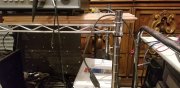
Last month Lee contacted me and inquired about upgrading an Acurus LS11 that he had. Because there are others on the forums here that use the Acurus pre's we thought that we'd make a thread out of it for others to watch and ask questions along the way. Lee's LS11 arrived yesterday so away we go... This LS11 is a very late production unit. This is evidenced by the black lower chassis and black back panel. These only came out from what I can tell in the last two years or so of production. One of the primary storage caps has a 15th week of '98 date code on it so this pre is at the latest a late '98 model but more likely a '99 or '00 model. I don't think that these were built much past the year 2000 after the Klipsch buy out.
For this work the entire power supply will be upgraded. The 5VA transformer is swapped for a 10VA, the standard 1 amp rectifier diodes are replaced with 2A soft recovery types. The 3,300uF primary storage caps are replaced with 8,200uF Nichicon's and the regulated DC rails receive new e-caps as well. The two primary storage caps will be bypassed with polypro film caps. A few of the incoming audio path resistors are replaced with Dale low noise metal films. In addition I had some boards built to house an LED biased current source for the front end complementary diff inputs. These small boards are designed to sit in the same locations as the LTP tail resistors. I typically see a modest reduction in THD+N across the 10Hz - 20kHz band with the addition of the active current sources.
Upon receiving a piece of gear for upgrade I will usually run a few tests on it to see if any glaring problems exist. As luck would have it this Acurus pre is one of the few I've ever seen that actually had a problem. Not a major problem mind you as its still passing the OEM THD+N spec, but it's not proper. I included a couple of charts from the AP to show what's going on with the pre. The first chart shows THD+N vs V-out. The left channel is basically a textbook curve for one of these Acurus pre's. Its what I expect to see, +/- a few dB of that line anyway. The right channel has issues and is showing about +5dB worse noise at higher voltages.
Moving on to the second chart (THD+N vs Freq) shows the same issue exists at higher frequencies. Once you drop below ~200Hz things are starting to look more normal for the right channel.
So I will need to correct this issue before moving on to the upgrade work.
I began by performing a the following checks on the preamp to isolate the problem. Voltage checks are good, resistances also look fine. DC offset is great, like 1mV in the problem channel and 20mV in the left channel, this is actually better than most Acurus pre's I've measured. Residual noise showed no issues as both channels were approximately 16.5uV. To eliminate the front end switches and potentiometers as a source of the noise I connected the AP's generator output directly to R4B which is the signal input resistor for the right channel just before the complementary diff inputs. Running a distortion test in this manner resulted in a curve nearly identical to the first THD vs V-out chart, so the switches and pots are not a problem.
I used up my freeze spray a few weeks back and haven't replaced it yet so I decided to try the opposite and use some heat to see if anything jumped out at me. I set my Weller solder station down to 300F and started probing while watching the distortion of the right channel on the AP. When I got to the inverting side of the Comp diff inputs both the PNP and NPN transistor showed a slight drop in the THD+N of 1 - 2dB when they were heated. A bit more probing and the source of the distortion popped up, the 10pF mica capacitor in the feedback network. Once I hit that with the heat and then moved the iron away from the mica cap the distortion would drop right down to match the Left channel. I then did the same thing again and ran a test. You can see that in the third chart the Right channel mostly follows the left. The distortion jumped back up a couple of times, but this Mica cap should be whats causing the elevated distortion issue. I have some 15pF caps so I may install one of them temporarily to test the issue until I can get some new 10pF caps in from Mouser.
Once this problem is out of the way and the preamp tests good I'll move on to the upgrade work.
 I had an RL-11 show up locally on CL a few months back, mint condition, original owner, included remote and box. Did I need it? NO! But at $200 I couldn't have driven to the North side of Dallas to get it any faster and not wound up in jail. Sometimes there's just no way to resist the deal... A few weeks later a very clean LS-11 showed up on CL for slightly less. I barely managed to talk myself down from buying that one by using the killer deal on the RL-11 to justify walking away.


")