- Joined
- Jun 20, 2013
- Messages
- 696
- Location
- Kapiti Coast, New Zealand
- Tagline
- Path under Coastlands overbridge
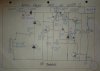
I have designed and built various designs of high efficiency switching step down, precision regulated, current limited voltage converters over the last 22 years. Most of these converter designs are self oscillating using discrete components. Foldback current limiting, adjustable under voltage lockout / threshold circuit are optional features of many of these circuit designs.
I prefer to use fixed component adjustments for reliability and stability.
Use top quality components well below their maximum ratings and encapsulate circuit using neutral cure silicon rubber to avoid maintenance but still make adjustment possible by changing fixed components, then re-sealing with neutral cure silicon rubber roof and gutter sealant.
Changing fixed components will be virtually impossible if epoxy resin encapsulation is used.
http://forums.phxaudiotape.com/showthread.php/6749-Voltage-Reduction?p=174019&viewfull=1#post174019
http://forums.phxaudiotape.com/showthread.php/1041-Bicycle-audio?p=104095&viewfull=1#post104095
Last edited: