Hi all. I'm brand new to the forum, and fairly new to vintage audio. Bear with me while I give you a brief summary of how I got to where I am now...
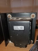
12 or so years ago, I bought a PL 400 and a pair of Dahlquist DQ-10's to "duplicate" a system one of my dad's best friends had (except he had a PL 700B). I was very happy with the sound although the 400 didn't drive the DQ-10's to quite the level I wanted. I then looked for a 700, and I found one on Craigslist that turned out to be a Clair 700 Series II. Of course, once I found out what I had, I was really happy. It's done a great job, but I never noticed much more gain than the 400, and it was always a bit imbalanced between the R and L channels. It looks mostly original except the electrolytic caps were replaced, and I think the drivers on the R channel were replaced (more on this below).
About a week ago, I decided to procure some test equipment and do some basic checks from the Service Manual. I know enough to be "dangerous", but I'm not ignorant to the safety precautions necessary around the main caps and the high DC voltage on the cans of the transistors, etc.
So the very first test is to ensure the clipping is symmetrical. I couldn't get the left channel to clip (on the scope), and the right channel only clipped with the input at 6V. I will admit that the basics of analog circuits often trip me up, so maybe there's some impedance issues I'm neglecting. I'm a Chemical Engineer by trade. I try to think in terms of pressure, flow, etc, but I haven't really grasped all the concepts yet. Actually, one of the reasons I started on this journey was to learn.
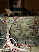
I've attached pics of the finals and drivers. I know the Clair units were ordered full complimentary, so the original schematics and info aren't quite right for this build. What jumped out at me was that the drivers are the same as the finals (drivers on the right were replaced with what I assume are equivalents). Is that correct? If so, I'll start checking the transistors one by one. Haven't checked bias yet.
Any info would be greatly appreciated!!
P.S. please ignore the dust on the transformer in the attached pic")
12 or so years ago, I bought a PL 400 and a pair of Dahlquist DQ-10's to "duplicate" a system one of my dad's best friends had (except he had a PL 700B). I was very happy with the sound although the 400 didn't drive the DQ-10's to quite the level I wanted. I then looked for a 700, and I found one on Craigslist that turned out to be a Clair 700 Series II. Of course, once I found out what I had, I was really happy. It's done a great job, but I never noticed much more gain than the 400, and it was always a bit imbalanced between the R and L channels. It looks mostly original except the electrolytic caps were replaced, and I think the drivers on the R channel were replaced (more on this below).
About a week ago, I decided to procure some test equipment and do some basic checks from the Service Manual. I know enough to be "dangerous", but I'm not ignorant to the safety precautions necessary around the main caps and the high DC voltage on the cans of the transistors, etc.
So the very first test is to ensure the clipping is symmetrical. I couldn't get the left channel to clip (on the scope), and the right channel only clipped with the input at 6V. I will admit that the basics of analog circuits often trip me up, so maybe there's some impedance issues I'm neglecting. I'm a Chemical Engineer by trade. I try to think in terms of pressure, flow, etc, but I haven't really grasped all the concepts yet. Actually, one of the reasons I started on this journey was to learn.
I've attached pics of the finals and drivers. I know the Clair units were ordered full complimentary, so the original schematics and info aren't quite right for this build. What jumped out at me was that the drivers are the same as the finals (drivers on the right were replaced with what I assume are equivalents). Is that correct? If so, I'll start checking the transistors one by one. Haven't checked bias yet.
Any info would be greatly appreciated!!
P.S. please ignore the dust on the transformer in the attached pic
Attachments
-
 2 MB Views: 28
 -
 2 MB Views: 29
 -
 1.5 MB Views: 27