Rev. A to Rev. E differences and Quasi vs Full

laatsch55

Administrator,
Staff member
Joined
Jan 14, 2011
Messages
74,968
Location
Gillette, Wyo.
Tagline
Halfbiass...Electron Herder and Backass Woof
#22
Whoa Nellie...
Technically, you are correct; but in practice that never happens. True, the total rail voltage in a PL700 is 200 volts and this does not change after a WOPL upgrade. But to say the power output is controlled by the rail voltage is incorrect. It would be more correct to say the output is "limited" by the rail voltage; and at 200 volts, that theoretical power would be 5000 watts (200 volts x 200 volts / 8 Ohms = 5000 watts) or 2500 watts per channel. It just ain't so.
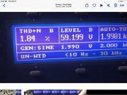
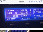
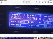
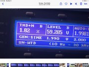
Now the magic of the WOPL upgrade is the increased efficiency in the front end and the higher SOA of the newer outputs. I routinely measure power output before the WOPL upgrade for my customers and have recorded voltages at the output of 52 vrms, 54 vrms, and 56 vrms per channel (338 watts, 364 watts, and 392 watts). After the WOPL upgrades, I was able to record output voltages of 62 vrms, 63 vrms, and 66 vrms (480 watts, 496 watts, and 545 watts). The peak power ratings are even higher, given the increased headroom and the ability to handle an increased input without clipping.
How is this possible? Closer tolerances during manufacturing, increased consistency, and design improvements thanks to WOA.

Try it yourself and see what your WOPL will produce. I would be surprised if you record less than 62 vrms at one channel when driven by a 1kHz signal at 2 vrms. There will be no clipping.

For a WOPL 400, you should be able to see the stock output of 44.72 vrms increase to at least 50 vrms (312 watts) per channel with no clipping.

I would agree with all this if you are driving only one channel.....
 

grapplesaw

Veteran and General Yakker
Joined
Aug 13, 2014
Messages
2,778
Location
Vancouver
Tagline
---
#25
Your clipping is test equipment threshold. Mine is by ear, so yeah, a little bit higher. And my hearing is not as good as it used to be. I'm down 1.2db at anything over 13 kHz.
So what you saying is your ear can determine clipping better than my Audio Precision and Teck scope. I just going to put the lot up for sale and listen more
 

mlucitt

Veteran and General Yakker
Joined
Jun 24, 2011
Messages
3,497
Location
Jacksonville, FL
#27
So what you saying is your ear can determine clipping better than my Audio Precision and Teck scope. I just going to put the lot up for sale and listen more
Glen, you took that exactly the wrong way. Your AP and scope are way more accurate and sensitive than my old ears. Your AP can pick up clipping before it is audible and I just keep cranking up the volume until I HEAR it, which is well past the threshold of your AP. That's why you have an AP.
 

grapplesaw

Veteran and General Yakker
Joined
Aug 13, 2014
Messages
2,778
Location
Vancouver
Tagline
---
#28
Glen, you took that exactly the wrong way. Your AP and scope are way more accurate and sensitive than my old ears. Your AP can pick up clipping before it is audible and I just keep cranking up the volume until I HEAR it, which is well past the threshold of your AP. That's why you have an AP.
Ok I got you. All good

I have never measured the voltage at 1-2% distortion. I will have to measure that and see how much gain there is. 1-2% distortion which is typical of most tube amps and not audible by most people I guess.

thanks for your input, after all I did ask for it I my post :)
 
Last edited:

mlucitt

Veteran and General Yakker
Joined
Jun 24, 2011
Messages
3,497
Location
Jacksonville, FL
#29
1-2% distortion which is typical of most tube amps and not audible by most people I guess.
Exactly why the WOPL is such a great amp compared to the original Phase Linear, which was a huge improvement over tube amplifiers. The Phase Linear amplifiers had so little distortion at high output levels compared to tube amps, hence their popularity with sound reinforcement folks. The WOPL has even less distortion so a proportionally higher "clean" output level.

When you have a pair of speakers that can handle 750-1000 Watts for a limited time, and you crank the WOPL amplifier wide open with a clean CD quality signal through a quality preamplifier, you are rewarded by an amazing Sound Pressure Level (SPL) at reasonable distortion levels.
 

mlucitt

Veteran and General Yakker
Joined
Jun 24, 2011
Messages
3,497
Location
Jacksonville, FL
#31
Here are some variations output voltages vs distortion
The second screen capture shows 451.5 Watts into 8 Ohms continuous per channel at 2.69% distortion and noise, maybe just beginning to be audible? That is with a generated 2kHz sine wave test signal at 2 volts, right? I wonder how that distortion and noise level compares to music program input at 2 volts? Same? More? Less?
That could be called a WOPL 900!

Thanks for the testing on the AP. I have got to get me one of those.
 
Joined
May 4, 2016
Messages
426
Location
Northeast Iowa
Tagline
Love great audio, beermaking and pyrotechnics
#32
Wow, you guys are really making me appreciate what I am going to build. I had already found from reading here that a 700 WOPL was probably better than about any amp within a normal persons budget. Now that I have the base I can't wait to build it.
 

grapplesaw

Veteran and General Yakker
Joined
Aug 13, 2014
Messages
2,778
Location
Vancouver
Tagline
---
#33
The second screen capture shows 451.5 Watts into 8 Ohms continuous per channel at 2.69% distortion and noise, maybe just beginning to be audible? That is with a generated 2kHz sine wave test signal at 2 volts, right? I wonder how that distortion and noise level compares to music program input at 2 volts? Same? More? Less?
That could be called a WOPL 900!

Thanks for the testing on the AP. I have got to get me one of those.
Yes 2khz generator signal. The AP output is set forr this series of photos at 2 volt. I use the volume pot on the amp to vary input current. Did not record actual input voltage at each level.

if you use a music signal as the input. I’d think no useful data could be measured. If you use a scope with a music signal it may be easier to pick up the clip that way.
 

Gepetto

Administrator
Staff member
Joined
May 15, 2011
Messages
14,086
Location
Sterling, MA
Tagline
Old 'Arn Enthusiast
#34
Yes 2khz generator signal. The AP output is set forr this series of photos at 2 volt. I use the volume pot on the amp to vary input current. Did not record actual input voltage at each level.

if you use a music signal as the input. I’d think no useful data could be measured. If you use a scope with a music signal it may be easier to pick up the clip that way.
With music, it will clip at a much higher level because the sine wave in this case is dragging down the bulk supply with the continuous nature of the sine wave input. Someone posted an article on the forum a while back about achieving higher practical headroom with an unregulated supply.
 

joe6072572883

New Around These Parts
Joined
Dec 3, 2024
Messages
1
#35
I'm a bit late to the party, but here are some thoughts:

The power supply rails in these amplifiers are unregulated, so the output will droop with big signals. The RMS limiting factor is likely the power transformer, and for peaks, such as in actual music, the amount of energy stored in the filter caps. If you're listening to something with a low peak-to-average ratio, it can be quite high for the occasional peak. If someone has a pair of high wattage dummy load resistors, it would be interesting to see what the transformer can put out with 120V in and a 4-ohm load on it. I would bring it up slowly on a variac, but I suspect it will flatten out long before 5KW. It would be really interesting to see.

Regarding the output difference, regardless of the power supply voltage, the quasi-complementary output stage has to go through two junctions on one half of its cycle and only one on the other. So, it will lose the power race by a whopping 0.7 volts or so. That works out to what, about 60mW? I think it may be that the clipping on the complementary output stage may not sound as bad. This is similar to how many people say a tube amp, with easily 2X the distortion of a solid-state amp, sounds better. I'm not playing favorites here, just pointing out that there may be sonic differences that are not reflected in the THD measurement.

A lot of people love full complementary designs. I'll admit, they look really pretty on paper, but it's also worth noting that PNP transistors are not the same as NPN transistors. Unfortunately, physics favors the N devices. Electrons are just a lot more mobile than holes. So, while the PNP device looks like the mirror of the NPN on paper, the PNP is a lot slower than the NPN—2 to 5 times slower. The PNP also tends to have more capacitive reactance at the base, making it harder to drive at high frequencies. This can be addressed, but unfortunately, it involves bringing the NPN device down to the PNP's level.

Next time you're looking at the nice symmetry of a fully complementary amp, remember that the devices are not exactly complements of each other. It's more like comparing a 1962 VW Beetle to a Porsche, at least speed-wise. But it looks pretty and may have some sonic benefits that defy simple measurements.

Also, this is more of a studio thing than a home audio thing, but both topologies have asymmetries. The complementary one is a bit more ethereal in that it doesn't show up on paper, but next time you're in the studio, if your mic preamp has an invert switch on it, try experimenting with it. Do sharp peaks, like from a drum kit (soloed to one mic so no phase cancellation issues), sound better one way or the other? It might seem like they do when going through the NPN device for the critical hard onslaught.
 
Top