Replacement for obsolete Q1 and Q2 transistors?

Sunnbobb

Journeyman
Joined
May 25, 2023
Messages
102
Location
Mount Vernon, WA
Tagline
Bikes, baseball and big amps.
#1
Working on a PL400 (different than the one with the DBt issue) and would like to replace the Q1 and Q2 TIS97 transistors as recommended by the manual to correct high DC offset. Mouser and Digikey both list the TIS97 as obsolete. Although Mouser lists a substitute, the specs for the sub don't match the TIS97. After hunting this site, I haven't found any discussion of a suitable replacement. What say you gurus?
 

George S.

Veteran and General Yakker
Joined
Feb 18, 2020
Messages
4,594
#2
That's a good question I've meant to ask as they use the TIS97 or the GES97 in the preamps also.
I researched this a couple years back and never found a suitable sub.
The guys who rebuild Mini-Moogs reportably demand original TIS97 from what I read.
There are also pinout variants of these transistors per Don "Watts abundant" posted docs.
 

Attachments

mlucitt

Veteran and General Yakker
Joined
Jun 24, 2011
Messages
3,375
Location
Jacksonville, FL
#7
As Lee can tell you, the key to getting the DC Offset low is to match the current gain, or hfe, of two TIS 97 (or TIS 93, they are close) because these transistors are used as a Differential Pair (sometimes called a "Long Tailed" Pair), common emitter configuration in each channel of the Phase Linear amplifier PCB, such as the PL 14A.

The bias point in the Phase Linear configuration is established by ensuring that a relatively constant current flows through the emitter resistor, R6. This is done by using a fairly high value resistor (200K Ohms in our case) or a current source which results in a relatively high voltage across it compared to the input range. This is where the name “long-tailed pair” comes in. With no differential input voltage (in other words, the transistor bases are at the same voltage) the bias current will be split equally between the two transistors. When a differential voltage appears, the current will increase in one transistor and decrease in the other, but their sum will remain constant. The common-mode gain is defined by the matching of the two stages and the “stiffness” of the resistor or current source at the emitter of the two transistors.

We used to buy them by the thousand and spend all night measuring the hfe and creating matching pairs. I think Lee got a pair down to 5mV, installed.
 

mlucitt

Veteran and General Yakker
Joined
Jun 24, 2011
Messages
3,375
Location
Jacksonville, FL
#9
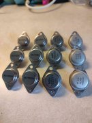
The mix of transistors I just removed from a customer's PL400 (not including the RCA410 Driver Transistors), I have mixed feelings of possible counterfeit MJ15024 devices:
3 Mix of Transistors.jpg
 
Joined
Apr 1, 2015
Messages
133
Tagline
---
#11
matched NPN's, why not try ksc1845's?
40v vs 120v
500mA vs 50mA
i doubt it approaches 50mA no less 500mA

tis93 is pnp and there are surface mount PRE-MATCHED dual chip packs with super tight matches (10.00 each ready to go)
 
Last edited:

mlucitt

Veteran and General Yakker
Joined
Jun 24, 2011
Messages
3,375
Location
Jacksonville, FL
#12
Yup, those are fakes. There are much better Chinese 15024 fakes out there, that are hard to tell from the real deal. Only way to know for sure is purchase from franchised distributors (and White Oak, we only purchases from franchised distributors :) .
The Left and Right channels were terribly unbalanced. After I installed the 12 (WOA) MJ21196G Output Transistors, the Left and Right channels were perfectly matched.
 
Top