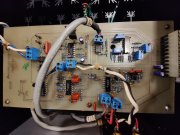
Rare beast NRG Control A401M class A monoblock

simonsayz69

New Around These Parts
Joined
Apr 27, 2022
Messages
8
#22
Fixed it and got it running. On the test bench now. The amp seems to be running fine but i am skeptical about the heating of the heat sinks. Initially before i fixed it the number 1 and four were heating up but now the number 2 and 3 are heating up on both the sides. The outborads are also warming up as they should. I have only changed one of the mosfets, should i change all four of them or two of them. As they are two different types applied in a pair. Help from senior members would be highly appreciated. Thanks in advance
 

laatsch55

Administrator,
Staff member
Joined
Jan 14, 2011
Messages
74,884
Location
Gillette, Wyo.
Tagline
Halfbiass...Electron Herder and Backass Woof
#23
Is there a bias circuit?? Whay does your offset look like. You should change out complementary pairs of outputs on those mosfets, better if you could match them. Not a deal breaker though..
 

simonsayz69

New Around These Parts
Joined
Apr 27, 2022
Messages
8
#24
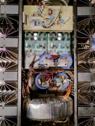
There are adjustment points but doing that without proper schematics and data, is way out of my league .i would try changing two of the same ones tomorrow and observe. also since this is a class A/ AB amp would it be possible that it runs in different modes with different pairs of transistors, although not seems to be a possibility but i am perplexed.
 

Attachments

J!m

Veteran and General Yakker
Joined
Dec 24, 2019
Messages
10,848
Location
Connecticut
Tagline
BOT
#25
I think the switchover point from A to AB would be determined by the initial bias setting, and not the components per se.

(Note I know enough to be dangerous)

I think you'd want to trace the runs on the board and determine what the trim pots are adjusting. Running it way out of whack for any length of time will kill it proper.

And I agree that components should be replaced in pairs, or a total replacement across the board (if possible). Some amps, like my Counterpoints, are not tolerant of replacements, as they had to be tightly matched from hundreds to get tens, long discontinued MOSFETS...
 

laatsch55

Administrator,
Staff member
Joined
Jan 14, 2011
Messages
74,884
Location
Gillette, Wyo.
Tagline
Halfbiass...Electron Herder and Backass Woof
#26
The TO-220 screwed to the heatsink has to be the bias transistor.
Are your new outputs also International Rectifier brand.
Look at the wiring of the output sockets. There will be emitter resistors ( I think). I am not familiar with this so I dont know if you measure bias off a bias resistor. See if there are 2 different resistors from the emitter resistors
.
 

simonsayz69

New Around These Parts
Joined
Apr 27, 2022
Messages
8
#27
Shall give it a try tomorrow and will also change both of them and give it a try. How ever the value of the other ones is unknown as nothing is specified on the schematics, i am glad to have found these forum and you guys who have helped me a lot. Thanks again.
 

simonsayz69

New Around These Parts
Joined
Apr 27, 2022
Messages
8
#28
Have tried changing the mosfets in a pair, the amp has gone in the protection mode. Trying to fix it, shall keep updated.
 
Top