I saw one of the guys over on AK had taken an old amp and installed 96's into it with 4-410's and it was giving him issues. I never really paid much attention to an old amp with new outputs in it since I only built complete WOPL amps but I know it will destroy itself with no other upgrades so he'll be looking for some answers over here. I recommended he come over for some answers from the pro's.

Putting in 96's into an old 700B
- Thread starter WOPL Sniffer
- Start date
One of the many problems with the quasi configuration, especially in the 700 (because you have more transistor cans than the 400) is that the lower half of the configuration has all the output transistor cans swinging with the output signal. The heatsinks that these sit on is DC ground. Thus all the surface area of the transistor cans mounted to the heatsink with a dielectric in between them sets up a capacitor to ground structure on the output signal. This effect is totally eliminated when you move to the full comp configuration.
Ever notice that the purple heatsinks are on the negative side of the signal?
Ever notice that the purple heatsinks are on the negative side of the signal?
The dielectric constant of mica (if mica is what they really meant) is higher than the sil-pads. Generally speaking, mica has a DC of ~7 and the sil pads range from 4-6 depending on which Bergquist material you select. The ones I recommend have a DC=4. The higher the DC, the higher the capacitance that is formed by these parallel plates.
If they really meant Kapton insulators, that DC is ~ 3.5 which is in the same range as the Sil-pads.
Thinner is also worse, since the capacitance formed is inversely proportional to the separation distance. Thus if the really thin sil-pads were chosen, that would make the capacitance larger.
Also generally speaking, full comp is best, it eliminates nearly all of such effects and makes the capacitance formed actually beneficial to the amps overall performance.
Oh exciting that my thread has found some attention!
Surprised that I am actually the first who did this (?). After I repaired the amp (94 volts on the right channel, defective VU meters) and after some unexpectedly long listening session it was clear to me, this thing is outstanding and it deserves a full restoration. Mainboard recapped, filter caps replaced and last but not least of course the output transistors.
Originally with all repairs the amp ran fine with the silicone pads and completely strange outputs (one side equipped with BU608 from ISC) and another with RCA 2N5240. All not original, but it worked. At the same time I also have twenty NEC 2SD555 here, also put these in, same phenomenon, but they are apparently known to run instable in that circuit. I thought that the MJ21196G were the best choice for the amplifier and would not give any further problems.
I'll try using base stoppers on the output triplet or bypass capacitors on Q7 and Q10, though I find it odd that the BU608 (newer output device, with a high fT) ran fine in them without any modification.
The answer will be: WOPL it, and yes, this will happen over the next few months, but I would like it to run again now.
I measured the insulators I have on hand with the Mitutoyo 293-765 (.00005") digital micrometer, Thickest (best) to Thinnest (worse):
Green Sil-Pad - .01230"
Bergquist Gray Sil-Pad - .00925"
Pink Sil-Pad - .00925"
Brand X Gray Sil-Pad - .00765"
Amber Kapton Pad - .00510"
Mica - .00225" to .00415"
Green Sil-Pad - .01230"
Bergquist Gray Sil-Pad - .00925"
Pink Sil-Pad - .00925"
Brand X Gray Sil-Pad - .00765"
Amber Kapton Pad - .00510"
Mica - .00225" to .00415"
Hi Mark, you need to take both thickness and dissipation factor into account to rank these from best to worst. And you also have to factor in thermal conductivity which usually degrades with increased thickness in materials of these sorts...
The variation in thickness materials was interesting. Only the mica varied from piece to piece, the others were consistently uniform in thickness.
- Joined
- Jan 14, 2011
- Messages
- 74,264
- Location
- Gillette, Wyo.
- Tagline
- Halfbiass...Electron Herder and Backass Woof
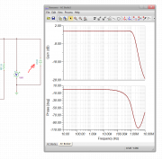
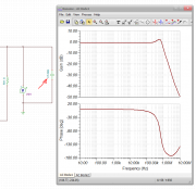
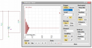
And here is the response of the PNP emulator in a PL700 when you consider the capacitive coupling effect of the 6 TO-3 transistor cases to the heat sinks. The lead network designed in is not enough to compensate for this effect. You can see the phase response dipping close to an unstable condition in the low MHz ranges
- Joined
- Jan 14, 2011
- Messages
- 74,264
- Location
- Gillette, Wyo.
- Tagline
- Halfbiass...Electron Herder and Backass Woof