
You are using an out of date browser. It may not display this or other websites correctly.
You should upgrade or use an alternative browser.
You should upgrade or use an alternative browser.
PL700B's...White Oak or Pine Box
- Thread starter Peter S
- Start date
- Joined
- Jan 14, 2011
- Messages
- 75,642
- Location
- Gillette, Wyo.
- Tagline
- Halfbiass...Electron Herder and Backass Woof
Yep.
Peter S
Journeyman
Thanks Lee, My Variac doesn't have enough umph to drive a PL into clipping, even one channel. Is the another way to test for current sharing?
grapplesaw
Veteran and General Yakker
I would take the varic out of circuit as you have successfully powered it upThanks Lee, My Variac doesn't have enough umph to drive a PL into clipping, even one channel. Is the another way to test for current sharing?
- Joined
- Jan 14, 2011
- Messages
- 75,642
- Location
- Gillette, Wyo.
- Tagline
- Halfbiass...Electron Herder and Backass Woof
Thanks Lee, My Variac doesn't have enough umph to drive a PL into clipping, even one channel. Is the another way to test for current sharing?
Not without risking amp failure...
Peter S
Journeyman
Amazing sticker! Held up after all these years!Looks like Val put this amp together
Peter S
Journeyman
Hi Glen, the manual wanted the line voltage reduced to 75% to measure emitter resistors. Do you think it would be OK to measure them at full voltage?I would take the varic out of circuit as you have successfully powered it up
- Joined
- Jan 14, 2011
- Messages
- 75,642
- Location
- Gillette, Wyo.
- Tagline
- Halfbiass...Electron Herder and Backass Woof
The objective of turning the voltage down is to bring the current up without going out of the SOA. I wouldn't be afraid to load it up at 4 ohms, at half voltage and then check across the emitter resistors..
grapplesaw
Veteran and General Yakker
My badHi Glen, the manual wanted the line voltage reduced to 75% to measure emitter resistors. Do you think it would be OK to measure them at full voltage?
I did not register that you were testing the emiter resistors. Though you were taking on the load test.
I guess I need to read the whole post.
Peter S
Journeyman
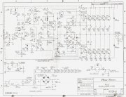
I just realized why the 'kink in the buss bars indicates a quasi complimentary amp. Does the insertion of R 41 in the path of output Q 14 not affect current balance?
only in full saturation of the negative rail side, other wise it is just a current sense resistor.
mlucitt
Veteran and General Yakker
6-1.4. Current sharing test. This test is necessary to verify that ALL outputs are operating properly, ensuring a permanent repair. Although the amplifier will probably meet all specs without all outputs operational, increased current loading of the remaining outputs will result in a significant reduction in reliability.
a) With an 8 ohm {dummy} load connected to the output terminals of the left channel, drive the left input with a 200 Hz signal to obtain 53 V RMS output. {using a Variac} Turn the line voltage down to 75 VAC. {prior to this step drop the amplifier Faceplate and Control Board forward onto a soft cloth to gain access the the back wall of the amplifier}
b) Using {a} DC voltmeter, measure the voltage drop across the {.33 Ohm} emitter resistors in each {left channel} output bank. Verify that there is between 150 mV and 180 mV DC across each {emitter} resistor.
c) Replace any output transistor whose emitter resistor reading varies more than 20% from the typical; verify first that the resistor itself is not damaged. {Repeat this test for the right channel}
From the PL700 Series II Service Manual (text in brackets was added by the technician)
Peter S
Journeyman
Thanks, so while attempting to check the bias, there was a pop and a rail fuse blew without an input signal. Replaced fuse and powered up with no load. Left output was 70 Volts DC with DBT. Pulled left chan outputs and drivers; still 11 Volts on speaker terminal (no load or input connected). Tested (in circuit) transistors on PL20B, all good. Compared voltages Left to Right. But then, all reverted to normal...Put drivers and outputs back and the amp seems to behave normally, 430 Watts into the dummy load. Is this the first PL to ever heal itself? Has anyone had an intermittent issue like this?
Carrying on to current sharing, my variac does not have sufficient capacity so hoping the following would show some indication; Using full line voltage, a 200 Hz signal drove the amp to 40 VAC output into 8 ohms. The worst column of output emitter resistors measured from 136 mV to 156 mV. I replaced the transistor with the lowest reading and now that Re measures 143 mV.
Beginning to have doubts about this bridging project! At the very least, temperature controlled fans would be a must. Are the emitter resistors capable of handling full output into a 4 ohm load? I recall the White Oak backplanes using higher precision E resistors which I would imagine would insure better current sharing but are they designed for a 4 ohm load?
grapplesaw
Veteran and General Yakker
“Beginning to have doubts about this bridging project! At the very least, temperature controlled fans would be a must. Are the emitter resistors capable of handling full output into a 4 ohm load?”
You should build an amp with all new components that are designed to be functional. Using all that old junk like carbon emitter resistors and old drivers probably will not live.
You should build an amp with all new components that are designed to be functional. Using all that old junk like carbon emitter resistors and old drivers probably will not live.
- Joined
- Jan 14, 2011
- Messages
- 75,642
- Location
- Gillette, Wyo.
- Tagline
- Halfbiass...Electron Herder and Backass Woof
Peter, you probably experienced a "latchup", where the driver board does not power up in the proper sequence. The Archives have a very good explanation of the phenomenon..
Peter S
Journeyman
Thanks Lee! I will search the forum. I am surprised that there was no damage and amp has powered up a number of times since, pushed to clipping and all good!
- Joined
- Jan 14, 2011
- Messages
- 75,642
- Location
- Gillette, Wyo.
- Tagline
- Halfbiass...Electron Herder and Backass Woof
I've had similiar experiences after replacing electro's on stock boards. It's not a rare occurance..
https://forums.phxaudiotape.com/thr...-up-tendency-in-phase-linear-amplifiers.2307/
https://forums.phxaudiotape.com/thr...-up-tendency-in-phase-linear-amplifiers.2307/
Peter S
Journeyman
I guess that means it could happen again at anytime. I found Joe's explanation;
https://forums.phxaudiotape.com/thr...-up-tendency-in-phase-linear-amplifiers.2307/
Will the component numbers correspond to the PL20B control board?, thanks again.
https://forums.phxaudiotape.com/thr...-up-tendency-in-phase-linear-amplifiers.2307/
Will the component numbers correspond to the PL20B control board?, thanks again.
Peter S
Journeyman
Still weighing pros and cons of bridging;
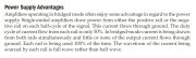
Here is an interesting excerpt from "Designing Audio Power Amplifiers" by Bob Cordell regarding power supply loading in bridged amplifiers.
Cooling fans will be a necessity of course, but 730 watts into 4 ohms (Phase Linear's spec) is 13.5 amps. How can the amplifier deliver this power when the maximum allowable ( PL manual ) fuse size is 8 amps? Is this because the rail fuses are only conducting for half of each cycle?
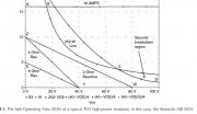
Is 4 ohm operation ( bridging with an 8 ohm load) threatening the SOA of MJ21196's? Attached is SOA curve(s) for an MJ15024 from D. Self's book "audio power amplifier design"
Here is an interesting excerpt from "Designing Audio Power Amplifiers" by Bob Cordell regarding power supply loading in bridged amplifiers.
Cooling fans will be a necessity of course, but 730 watts into 4 ohms (Phase Linear's spec) is 13.5 amps. How can the amplifier deliver this power when the maximum allowable ( PL manual ) fuse size is 8 amps? Is this because the rail fuses are only conducting for half of each cycle?
Is 4 ohm operation ( bridging with an 8 ohm load) threatening the SOA of MJ21196's? Attached is SOA curve(s) for an MJ15024 from D. Self's book "audio power amplifier design"
Attachments
Last edited: