PL700 Upgrade

BobPep

New Around These Parts
Joined
Feb 29, 2024
Messages
3
Location
West Hempstead, New York
Tagline
Love spending time with my kids and grandkids
#1
Hi,

Out with the old and in with the new.

Brewstraveler has shipped his speaker protection kit.

Submitted a parts order to White Oak Audio:
New 15K uf caps, rectifier bridge, and bus bar for now.

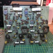
Due to time constraints, I decided to go with Mark Lucitt’s new control boards which I believe progress.

Thinking of keeping the old PL0171 control board and updating parts on it to have as spare. Just in case.

Also, planning on installing a soft start circuit, if feasible.

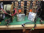
VU meters are in sad shape but light. I read somewhere that you can test them with a “AA” battery and resistor. Not sure?

Going to order resistors and capacitors for the output transistor’s backplane. Any suggestions?

Power switch works under no load. Any replacements available?

Any other suggestions are welcome. Thanks.
 

Attachments

wattsabundant

Chief Journeyman
Joined
Apr 26, 2011
Messages
932
Location
Central Ohio
#2
I have the original rotary power switch used in the 700B and I assume that was what was in the 700. The switch was prone to failure as it was misapplied. Adding a soft start would be nearly impossible due to space constraints. I have a solid-state switch.(trriac) that mounts on a small board. The board mounts on the lower screw that supports the driver board. I haven’t put this board in a 700, only 700B and 700II. It should be pretty simple though.
 
Last edited:

wattsabundant

Chief Journeyman
Joined
Apr 26, 2011
Messages
932
Location
Central Ohio
#4
To test the meters, a person could take any 1.5v battery, and a series 100K pot or so, and adjust the pot for full scale on the meter. It will be important to make sure the pot is at maximum resistance before making the connection. Otherwise the battery will turn the unobtanium meter into a one revolution motor.
 

wattsabundant

Chief Journeyman
Joined
Apr 26, 2011
Messages
932
Location
Central Ohio
#5
Here is a video showing the addition of a soft start circuit to an original 700.

The 4 ohm resistor limits the current to about 30 amps (Ohms law says 120V divided by 4 ohms = 30 amps) . I recorded peak currents in the 150 amp range when developing the triac board so limiting the current to 30 amps likely a good compromise.

When using this type of of start, It is imperative that some disconnecting means, be it a relay board like I offer or something else is installed on the amplifier output. The reason being that there is a race condition for the amplifier to stabilize as the DC voltage on the main caps rises. Initially, there will be a DC offset on the amplifier output at the instant power is applied and the speaker will load down the power supply preventing the DC voltage from rising. The result will most likely burn up the 4 ohm resistor.

The relay board has a few second time delay so the amp doesn't see the speaker load until the input differential amplifier stabilizes.

What does all this mean? I'm guessing it's no accident that a 4 ohm resistor was picked. Anybody who decides to go this route should stick to the values presented. Hats off to Scott for a great job getting it all packaged neatly in the chassis.
 
Last edited:

Hexis22

Chief Journeyman
Joined
Dec 28, 2022
Messages
677
Location
Wisconsin
#7
Hi, Could you provide a part number for the contactor you used?

Thanks in advance,

dognort
Sorry if that post was misleading, that's not my video. I just provided a link for reference.

You should be able to find the contactor based on part number shown in the video.

 
Top