- Joined
- Jan 14, 2011
- Messages
- 75,894
- Location
- Gillette, Wyo.
- Tagline
- Halfbiass...Electron Herder and Backass Woof
A no clean cleaner? Reminds me of condensate..


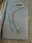
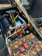
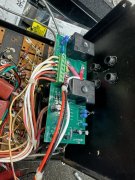
All grounds should terminate back to the main capacitor buss bar.Relay position six has three wires, a thin white/red wire that heads to new control board, a new white ground wire to ground of input jack and the original white wire that connects to the left main cap + (upper) terminal.
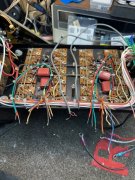
I am starting to understand why folks do the full WOPL upgrade. That backplane is unreal, yuck. Anyways for now will carry on. Fixed the wiring as detailed above. Now ready to install new control board and darned if I can find anywhere on the schematics how those output sockets are numbered. So perhaps yet another helping hand with the picture I posted above?
I have just about everything Lee. Pretty sure that I know as much about PL 400/700 amps as the founder did/does. I documented a lot more.Perfect wow ty sir.
