PL700 PRO Restoration

flawsjef

New Around These Parts
Joined
Nov 12, 2022
Messages
7
Location
Minnesota, USA - "Bambi Land"
Tagline
"I just want to play Jerry right ... "
#1
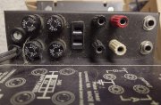
This old beast has been with me for maybe 25 years, did great service for tops and monitors. Figured it deserved a good going-over before putting it back to work, has been laying fallow for ... far too long. Previously mentioned this in a thread for PL Manuals, and was asked to post some images ... so here is what we are starting with.

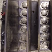
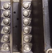
Most of the transistors appear to be original, and obviously this version is the "fully complimentary" design. No doubt, will be replacing the silipads or whatever with real Mica and real Thermalcote.

Was gigging just fine when last out in the wild, there was an isolated episode of one channel fading but that was an "extreme" circumstance, with a greviously low impedance load ... never had motivation to reproduce the problem. Ran it hard for another half year after that, no recurrence. Back in 1999, received a tip about this problem, suggested the power resistors on main PCB.
700 Face W.jpg 700 Resistor Tip.jpg 700 IO.jpg 700 Top VU.jpg 700 Chassis Top.jpg 700 Chassis Bottom A.jpg 700 Chassis Bottom B.jpg 700 Transistors A.jpg 700 Transistors B.jpg
 

wattsabundant

Chief Journeyman
Joined
Apr 26, 2011
Messages
933
Location
Central Ohio
#3
I agree with Sniff on the silpads. No reason to go back to mica. With few exceptions, power transistors are run until fail. Yes, there are newer devices with slightly better characteristics such as safe operating area. When I test an amp I get it nice and hot and check the output case temperatures with with a thermal gun. Anything over about 85 degrees C would be a concern. More importantly, all of them should be within 5 degrees C of the average.

Attached is the 700 manual. If you have the test gear, perform the tests per section 5 and also current sharing test in section 6-1.4. The 400 manual is also attached as it has service bulletins that are missing in the 700 manual.
 

Attachments

WOPL Sniffer

Veteran and General Yakker
Joined
Aug 10, 2015
Messages
11,522
Location
Minnie-Soda
Tagline
Screw it
#4
When the company Tech's maintained these, they switched them to SilPads for a reason. Not only because the Whale Spooge is hard to clean off. I'll bet some even came with SilPads
 

WOPL Sniffer

Veteran and General Yakker
Joined
Aug 10, 2015
Messages
11,522
Location
Minnie-Soda
Tagline
Screw it
#5
We have had guys here have 40 year old transistors go POOF...... I don't believe we have seen any NEW ones go poof unless there was a screw up. The outputs take the brunt of the beating on these amps so why wouldn't you spend $100 and use the best???? THAT is the best way to go. One less thing to worry about. It won't be cool to start granny's shag carpet on fire when the shrapnel flys from old junk going POOF!!!
 

flawsjef

New Around These Parts
Joined
Nov 12, 2022
Messages
7
Location
Minnesota, USA - "Bambi Land"
Tagline
"I just want to play Jerry right ... "
#6
I agree with Sniff on the silpads. No reason to go back to mica. With few exceptions, power transistors are run until fail. Yes, there are newer devices with slightly better characteristics such as safe operating area. When I test an amp I get it nice and hot and check the output case temperatures with with a thermal gun. Anything over about 85 degrees C would be a concern. More importantly, all of them should be within 5 degrees C of the average.

Attached is the 700 manual. If you have the test gear, perform the tests per section 5 and also current sharing test in section 6-1.4. The 400 manual is also attached as it has service bulletins that are missing in the 700 manual.
"THANK YOU" for sharing the manuals - will be most helpful. The updates in the back of the 400 manual appear to cover the Pro 700 ... :)

----

I have a modest but "interesting" collection of amplifiers. This PL 700 is a one-off for me, and I am sort of looking at it to push some various mid-hi applications. "OR" it might wind up pushing a pair of EV DL18MT's depending which amp racks wind up where. It does share same/similar silicon requirements with AB International models, which I have a bunch of (9220/900's and 9420/1100's) ... so being able to stay in MJ15024/MJ15025 land makes life a lot easier.
 

MusicSteve

Journeyman
Joined
Mar 6, 2022
Messages
359
Location
Minnesota
Tagline
Always Thinking Outside The Box.
#7
This old beast has been with me for maybe 25 years, did great service for tops and monitors. Figured it deserved a good going-over before putting it back to work, has been laying fallow for ... far too long. Previously mentioned this in a thread for PL Manuals, and was asked to post some images ... so here is what we are starting with.

Most of the transistors appear to be original, and obviously this version is the "fully complimentary" design. No doubt, will be replacing the silipads or whatever with real Mica and real Thermalcote.

Was gigging just fine when last out in the wild, there was an isolated episode of one channel fading but that was an "extreme" circumstance, with a greviously low impedance load ... never had motivation to reproduce the problem. Ran it hard for another half year after that, no recurrence. Back in 1999, received a tip about this problem, suggested the power resistors on main PCB.
View attachment 71704 View attachment 71705 View attachment 71706 View attachment 71707 View attachment 71708 View attachment 71709 View attachment 71710 View attachment 71711 View attachment 71712
If you look at the left side of the board, the 2-big white resistors are 7.5k so your good their. I would add a Speaker protection board and a Capacitor kit from Joe to start w good luck
 

FredR

Veteran and General Yakker
Joined
Jan 26, 2014
Messages
1,529
Location
DFW
Tagline
WTF?
#9
Nice amp! What most of us do is gut the amp to the chassis wall and rebuild with Gepetto's parts from White Oak. Many good reasons to do that, but the original is a thing of beauty. Although my wife would disagree. ;)
 

flawsjef

New Around These Parts
Joined
Nov 12, 2022
Messages
7
Location
Minnesota, USA - "Bambi Land"
Tagline
"I just want to play Jerry right ... "
#11
From above, agree about the 7.5K resistors already being in place.
Got around to defacing, errr, pulling the front panel off ...
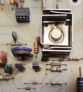
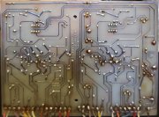
So here are some more images of what is going on. Looks to be relatively unmolested.
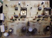
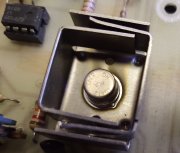
Noticed some discolouration ( THERMAL ?? ) around one of those old RCA 40412's ... also some as yet unidentified yukk nearby on the component side of the PCB.
Would not be surprised if it was beer splash or water, or God only knows what ... it was exposed to musicians without protection.
Notice one of the 0.33 Ohm Collector EMITTER resistors has apparently been replaced, nice soldering job whoever did it.
Glad to see the 351 OpAmps ...
Odd amount of soldering snot on the trace side, can't be sure it that is factory or re-work.
Given different discussions on intermittent/failure issues with the 40412's ... would make sense to replace those at the start. Apparently 2N3439 is appropriate. Saw a pair of the 40412's in the wild ... with 40 year old date codes ... even with NOS still a roll of the dice at best.
Step one here, is to "kit up" all the appropriate parts for the refurb ... this is a "copious free time" sort of project, as are many ... but having all the required bits and pieces in-hand beore starting makes the actual bench time much more productive.
Do I just grab the transistor replacement kit out there in eBay land for this ?
There is an "easy button" quality to that approach.

Thanks to the several of you who are watching the start of this. Your suggestions have been and will continue to be much appreciated.

( edit to correct 'collector' to 'emitter.' )

700 Interior IMG_20221204_141103845 cr.jpg 700 Board Component Side IMG_20221204_141912815 cr.jpg 40412 Unhappy IMG_20221204_141821800 cr.jpg Contrast IMG_20221204_141912815 cr.jpg
Board Foil Side IMG_20221204_141705817 cr.jpg 700 Chassis IMG_20221204_141623853 cr.jpg
 
Last edited:

wattsabundant

Chief Journeyman
Joined
Apr 26, 2011
Messages
933
Location
Central Ohio
#12
With few exceptions, i don't change out transistors that haven't failed. Joe has commented before that the 40412 operates outside of it's safe operating area. However it's 40 years old. I can say all of my series II amps that have the original control board still have the original 40412. Although the emitter resistor that was changed was done professionally, I would consider changing it to the same type of wire wound as the original. At a minimum the current sharing test called out in the manual should be performed. Also it wouldn't hurt to check the zener diodes to verify the voltage is very close to 15 VDC.
 

laatsch55

Administrator,
Staff member
Joined
Jan 14, 2011
Messages
74,874
Location
Gillette, Wyo.
Tagline
Halfbiass...Electron Herder and Backass Woof
#13
And if you run the 3439 get the biggest heatsink you can get for it. Their TO-39's and I got some 4 layer HS 's for them...
 
Top