PL400

Mark Stanley

New Around These Parts
Joined
Jan 12, 2021
Messages
12
#1
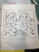
Hi. I’m brand new to this forum. Not sure if I am in the right place but I need some help with a PL 400. Picked it up a few months ago in a none working condition. I think it is a very very early model. It has 6 variable resistors on the board and I can’t find a service manual or schematic for this exact board. Any help would be greatly appreciated.
 

mlucitt

Veteran and General Yakker
Joined
Jun 24, 2011
Messages
3,339
Location
Jacksonville, FL
#2
Welcome, Mark. We are here to help. We thrive on pictures of the inside and outside of the amplifier and data from the plate on the back of the transformer if it is still there. Please give us the symptoms you experienced. It is not necessary or desirable for you to power up your wonderful PL400, you risk more damage by doing that.

We can bring this beauty back to life and you can begin to enjoy it once again. We can guide you if you have some electronics experience or you can send the amplifier to one of the techs here to do the work if you are not comfortable working inside the amplifier.
 

Mark Stanley

New Around These Parts
Joined
Jan 12, 2021
Messages
12
#3
Thanks for the warm welcome. I have the service manual off hifiengine but it doesn’t show my board. The board it shows has 4 trim pots but mine has 6. Also a comparison of the resistors indicates some differences. I suspect 2 of the trim pots are for the bias and 2 for the offset but what are the others for? The amp was blown when I got it and would not work. It is now recapped, several burnt resistors replaced, all the transistors on the board have been replaced with matched originals. On a variac it plays at low voltage but seems it has high bias that I can’t adjust out. Any suggestions?
 

laatsch55

Administrator,
Staff member
Joined
Jan 14, 2011
Messages
74,124
Location
Gillette, Wyo.
Tagline
Halfbiass...Electron Herder and Backass Woof
#4
There are 2 pots on each side on the board to adjust offset. Then, there are one on each side of the board in the middle of the board for bias.
 

Mark Stanley

New Around These Parts
Joined
Jan 12, 2021
Messages
12
#8
Thank you for all the help. I have looked at the white oaks upgrades on line. Looks like something to consider. Would still like to get the original equipment up and running if possible. Whenever I start bringing the voltage up slowly it starts to draw too many amps. When it starts to draw one amp I back it off. In other equipment I have worked on this would indicate to me a transistor problem but they all check good. Also when I turn it off the voltage on the positive voltage rail will drop right off but the negative voltage will not. It will still test negative 20 minutes after it is turned off. Any thoughts?
 

wattsabundant

Chief Journeyman
Joined
Apr 26, 2011
Messages
842
Location
Central Ohio
#10
Here is the service manual. Do yourself a favor and read it cover to cover, especially the troubleshooting section.

Do you know which channel has the issue? A variac doesn't limit current. A generally accedpted practice is to insert a 100 watt incandescent light bulb in series with the line cord. This is often referred to as dim bulb test set. Do a search on it.

If it's not latch up a possible problem is a bias failure that turns the outputs full on. A jumper wire from the cathode of D7 (banded end) to the anode of D6 ( same as tying base of Q7 & Q8 together) reduces bias to zero.

All this said, I'm in favor of checking every P/N junction, in circuit, and looking for shorted devices. If one channel works then you have a reference.
 

Attachments

Mark Stanley

New Around These Parts
Joined
Jan 12, 2021
Messages
12
#12
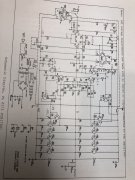
I still fell very uncomfortable not having a schematic for this board. I have read the service manual as advised and examined the schematics listed with the service manual and none of the schematics show my exact board. I can’t believe this board has no published schematic but maybe it doesn’t.
 

marcok

Chief Journeyman
Joined
Jun 9, 2014
Messages
988
Location
Milan Italy
Tagline
I'm very curious about any tech item
#13
First of all , welcome .
Check the number of your board ; it should be PL 0171 .
It was mounted on PL 700 .
It has 6 trims : input DC offset , output DC offset and bias . ( x 2 )
Schematics are available on PL 700B rev .1
Probably old models used this kind of board .
Ciao
Marco
 

Gepetto

Administrator
Staff member
Joined
May 15, 2011
Messages
13,473
Location
Sterling, MA
Tagline
Old 'Arn Enthusiast
#15
I still fell very uncomfortable not having a schematic for this board. I have read the service manual as advised and examined the schematics listed with the service manual and none of the schematics show my exact board. I can’t believe this board has no published schematic but maybe it doesn’t.
I posted a picture of the PL0171 schematic in an adjacent thread that Andrew is running just yesterday. The PL0171 has 3 pots per channel, bias, input DC, output DC adjustments.
 

mlucitt

Veteran and General Yakker
Joined
Jun 24, 2011
Messages
3,339
Location
Jacksonville, FL
#19
Interesting that a PL700 (not PL700B or PL700 Series II) control board would end up in a PL400, maybe an owner did it? Have we ever seen this before?
Mark, can you upload a picture of the data on the back of the transformer.
 
Top