PL 700 II Clair Bros Rising from the Ashes

Peter S

Journeyman
Joined
Jun 29, 2019
Messages
312
Location
Ontario Canada
#21
Thanks Guys!
You all make me feel very welcome. The 'boss' says play time is over for today. Quick question, I see main filter caps a White Oaks, does Joe also sell output transistors? or can anyone recommend a good source (preferably with distributors in Canada?) I have actually bought a set of counterfeits about 6 months ago.
 

Gepetto

Administrator
Staff member
Joined
May 15, 2011
Messages
13,944
Location
Sterling, MA
Tagline
Old 'Arn Enthusiast
#23
I could be on to something;
First, I couldn't resist 'getting the kinks out'. Not a priority, but the bent chassis bothered me! Looks like the amp, in a rack, possibly, fell forward. I rigged up this arrangement to carefully straighten it.
I use a similar large C-clamp process to straighten out bent chassis that has been used on a couple amps that I acquired along the way.
 

Peter S

Journeyman
Joined
Jun 29, 2019
Messages
312
Location
Ontario Canada
#24
Hi Folks;
It was suggested that the PL 36 board be replaced rather than repaired, but as per Joe of White Oak suggested; I should find the problem in the amp before upgrading. I believe the leaky cap, C 211 looks like it could be the culprit? (Seems to be directly involved in the signal path). I would like to repair this board rather than replace it for a few reasons;
The amp that I would like to "WOPL" for system, is the second amp in this recent acquisition, which is a full complimentary.

My Question;
Does anyone have, or know of a schematic for the "Clair Bros" series II? The first glaring difference seems to be R1 and R2. My amp uses 8.2 k ohm, 5 Watt's. Much higher value than I've seen on other amps or schematics. I have seen the PCB discolored around these resistors on other amps, but I presume the higher R value helped this problem. The resistors are also on stand-offs. Is this only on Clair Bros amps?

2nd Question;
The leaky cap ( C211 ) is 100 ufd, 10 V on the board, all schematics I have seen, call for 100 ufd, 6.3V ? What should I use? I heard that using an electrolytic with an 'over-kill' voltage rating can not allow the cap to function properly.
 

Attachments

Gepetto

Administrator
Staff member
Joined
May 15, 2011
Messages
13,944
Location
Sterling, MA
Tagline
Old 'Arn Enthusiast
#25
Hi Folks;
It was suggested that the PL 36 board be replaced rather than repaired, but as per Joe of White Oak suggested; I should find the problem in the amp before upgrading. I believe the leaky cap, C 211 looks like it could be the culprit? (Seems to be directly involved in the signal path). I would like to repair this board rather than replace it for a few reasons;
The amp that I would like to "WOPL" for system, is the second amp in this recent acquisition, which is a full complimentary.

My Question;
Does anyone have, or know of a schematic for the "Clair Bros" series II? The first glaring difference seems to be R1 and R2. My amp uses 8.2 k ohm, 5 Watt's. Much higher value than I've seen on other amps or schematics. I have seen the PCB discolored around these resistors on other amps, but I presume the higher R value helped this problem. The resistors are also on stand-offs. Is this only on Clair Bros amps?

2nd Question;
The leaky cap ( C211 ) is 100 ufd, 10 V on the board, all schematics I have seen, call for 100 ufd, 6.3V ? What should I use? I heard that using an electrolytic with an 'over-kill' voltage rating can not allow the cap to function properly.
I call BS on the 2nd issue Pete
 

Peter S

Journeyman
Joined
Jun 29, 2019
Messages
312
Location
Ontario Canada
#28
Thanks Gepetto. The 10V cap failed, so I will look for a 16V.
I thought I read something about it taking a certain percentage of the design voltage for the electrolyte to form or do something magical?
Came across it when I was studying cap 'reforming'.
 

mlucitt

Veteran and General Yakker
Joined
Jun 24, 2011
Messages
3,469
Location
Jacksonville, FL
#29
Thanks Gepetto. The 10V cap failed, so I will look for a 16V.
I thought I read something about it taking a certain percentage of the design voltage for the electrolyte to form or do something magical?
Came across it when I was studying cap 'reforming'.
On the schematic I have, I swear C111/C211 reads 100/63 and not 100/6.3. 63V seems high for that DC shunt application (is that right Joe?), but then that might be a reason for the 10V cap to fail. I don't have a PL36 board to look at, so I could be wrong. But if a 100/63 cap fits, I might try it, can't hurt.
 

oldphaser

Chief Journeyman
Joined
Sep 8, 2012
Messages
848
#30
The 100uF cap was never 63 volts. The schematics are sometimes hard to read and may be missing the decimal. The Phase Linear amps used either 6.3 or 10 volt caps. When the amplifiers failed these would sometimes fail as well. Going up in voltage in not a bad idea.
 

Peter S

Journeyman
Joined
Jun 29, 2019
Messages
312
Location
Ontario Canada
#31
So I replaced the leaky (C 211) cap with a 100 ufd 50 V . The oscillation is gone at 5 V P to P, but returns at about 10 V rms into an 8 ohm load. The PL 36 board looks like it has gone through some drama, but I would really just like to repair this amp rather than upgrade it right now. I had a quick peak at the full complimentary amp that I picked up with this one, and besides the main filter caps missing, the input op amp IC's are also missing!
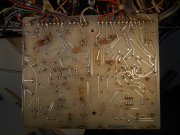
Attached is the Quasi amp's PL 36, BTW, is the PL 36 identical is a complimentary and quasi amp? ---and what are those caps (ceramic?) on the bottom of the PCB; an attempt at reducing oscillation?
Thanks for any guidance, Peter
 

Attachments

oldphaser

Chief Journeyman
Joined
Sep 8, 2012
Messages
848
#32
So I replaced the leaky (C 211) cap with a 100 ufd 50 V . The oscillation is gone at 5 V P to P, but returns at about 10 V rms into an 8 ohm load. The PL 36 board looks like it has gone through some drama, but I would really just like to repair this amp rather than upgrade it right now. I had a quick peak at the full complimentary amp that I picked up with this one, and besides the main filter caps missing, the input op amp IC's are also missing!
Attached is the Quasi amp's PL 36, BTW, is the PL 36 identical is a complimentary and quasi amp? ---and what are those caps (ceramic?) on the bottom of the PCB; an attempt at reducing oscillation?
Thanks for any guidance, Peter
Peter,

The PL36 pc board can be used for either quasi or fully complementary output with some removal of some parts from the quasi version and some jumpers installed. The output stage would also need some re-wiring and (2) additional wires going to each channel on the pc board. Use your fully comp amp as an example.

It appears that this board has already been worked over at one time in the past.

The ceramic disc caps on the bottom side of the pc board was indeed installed to eliminate oscillations. However, generally the caps are not needed on both the positive and negative pre-drivers even though it shows an example of this one of the Phase Linear service bulletins. The lowest value "slow down" caps should only be used to eliminate the oscillations. Starting with each channel one at at a time and looking at the oscillations on an oscilloscope (being feed from the output of a distortion analyzer) and determining whether it needs to be applied to the positive or negative pre-driver. Arbitrarily installing larger than needed slow down caps can sometimes cause oscillations. The amp should also be driven with a signal generator set to 20kHz at rated output (approx 53 volts into an 8 ohm load) to see these oscillations. Proper test equipment, knowledge and experience come into play here.

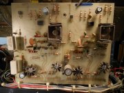
How about a photo of the top side of the pc board?

Also, if there are Rockwood brand 7.5K ohm 3 watt resistors (located on the Malco pins on the side of the board nearest the power supply capacitors) they should be replaced. The Rockwood's had a higher than normal failure rate and should be replaced with 7.5K ohm 5 watt resistors. (NOTE: The 7.5K ohm resistors were used when Phase Linear began using the LF351 IC's.) Earlier pc boards that used LF356's used 2.4K ohm 5 watt resistors.

There are also (2) 7.5K ohm 2 watt resistors located near the bottom of the pc board. One for each channel. These also should be replaced as a matter of course as they have been going up in value with age, heat, etc.

Ed
 

Peter S

Journeyman
Joined
Jun 29, 2019
Messages
312
Location
Ontario Canada
#33
Hi Ed;
Thanks for the detailed response. It seems that the right thing to do is convert this amp to full complimentary. I am thinking this is 'biting of more than I can chew'. Yes, I would have the other full-comp amp to copy. I was actually getting concerned about having a new set of output transistors driven by such a patched up PL 36.
I thought the board looked "up to date" because R1 and R2, where higher resistance 8.2 k ohms (less heat?) They are raised by pins, are those the "malco" pins, I assume?----learning all the time!

I will momentarily have another look at the full quasi amp, just to make a shopping list for White Oak. With your help, I would like to verify the functioning of at least the power transformer, bridge and LED displays,
 

Attachments

oldphaser

Chief Journeyman
Joined
Sep 8, 2012
Messages
848
#34
Hi Ed;
Thanks for the detailed response. It seems that the right thing to do is convert this amp to full complimentary. I am thinking this is 'biting of more than I can chew'. Yes, I would have the other full-comp amp to copy. I was actually getting concerned about having a new set of output transistors driven by such a patched up PL 36.
I thought the board looked "up to date" because R1 and R2, where higher resistance 8.2 k ohms (less heat?) They are raised by pins, are those the "malco" pins, I assume?----learning all the time!

I will momentarily have another look at the full quasi amp, just to make a shopping list for White Oak. With your help, I would like to verify the functioning of at least the power transformer, bridge and LED displays,
The 8.2K resistors are indeed the ones on the Malco pins. It appears that at least one of them I can actually see writing on; "IRC 8717 PW5 8.2K 10%". IRC is the manufacturer, 8717 is the date code; 17th week of 1987, and PW5 is a 5 watt resistor. So this was not a factory repair. I am not an electrical engineer so I can't debate the fine merits of what resistor value would work best. Therefore, I will stick with what the factory used when LF351 IC's are installed.... which was initially the Rockwood brand 7.5K 3 watt resistors with a higher than normal failure rate and then (because of the failures) the TRW PW5 7.5K ohm 5 watt resistor. Depending upon availability of a 5 watt resistor, a slightly higher wattage will also do say 7 to 10 watts.

It also appears that the 3.9K ohm 1/2 watt resistor in the left channel is toast and should be replaced. I would also check the protection circuit transistors which are located nearby. Usually at least one of them will fail also when a 3.9K is bad. Additionally you may find a bad pre-driver transistor and a 1N4148 diode on that channel as well.

Ed
 

Peter S

Journeyman
Joined
Jun 29, 2019
Messages
312
Location
Ontario Canada
#38
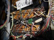
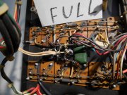
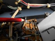
Here is something baffling! The cover screws were replaced and are slightly longer. The screw shorts the B- rail to ground. Should the hole have been shifted to one side to avoid this accident waiting to happen? Is this only on the Clair Bros steel chassis?
 

Attachments

Peter S

Journeyman
Joined
Jun 29, 2019
Messages
312
Location
Ontario Canada
#40
Hi Folks;
Work seems to be getting in the way of Phase fun again! My project has also taken a left turn as my scope developed a problem. Sorry if this is getting off-track. Proper trouble-shooting of this Leader LBO 516 is beyond my skill level, but I'm not giving up yet. In my opinion, it is a a well made unit, perfect for my purposes ( 100 MHz, multi trace ), but the cost of repair would probably exceed a used replacement. Besides, sending it to a shop is somehow 'admitting defeat'!

Any and all guidance would be appreciated;
The scope blanks out within 5 to 8 minutes of on time. Tapping on the main pcb (particularely) the 5 low voltage bridge rectifiers can cause the image to flicker, or blank out permanently as it warms up. I have used compressed air in this general area and actually watched the image fade back in, slowly. I have measured the DC voltage on the bridges (and associated filter caps ) and found no difference between working and failure mode.

Question; What kind of device (resistor or capacitor or semiconductor? or bad solder joint/crack) fails this way. I thought I was on to something when I watched the trace slowly come back as I blasted the pcb with compressed air. Electrolytics seem to cause more than their fair share of troubles, but would cooling with air restore them?

Thanks, Peter in Canada
 

Attachments

Top