
You are using an out of date browser. It may not display this or other websites correctly.
You should upgrade or use an alternative browser.
You should upgrade or use an alternative browser.
Phase Linear Dual 500 Diagnosis Assistance Requested
- Thread starter zeppelinofled69
- Start date
-
- Tags
- dual 500 phase linear

zeppelinofled69
New Around These Parts
- Joined
- Feb 9, 2019
- Messages
- 37
Thanks for the schematics Ed.
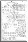
I doubt Q106, Z101 or Q102 will have any bearing on bias. Can I assume you are measuring bias across R133 and 145? The 10 ohm resistors?
You might experiment with R112 moving up from 680 ohms to closer to 1K. That may give you your adjustment back.
Other than the bias transistor itself which may be suffering from low gain, the transistors that have the most profound effect on bias are Q101, Q107, Q108, Q117. If the base-emitter drop of these devices has dropped over the years, you will have a hard time getting the bias down.
I have finally received the new output devices. After putting them in and making sure they were isolated properly from the heat sink, I started it up and all appears to be well with the amp.
Only thing that concerns me is the Bias sits just under the max threshold of .6V with the bias pot turned all the way down.
I have ordered new bias transistors, but I am wondering if this will actually fix the problem? Or is the wall voltage too high causing the circuit to be higher voltage than it should be?
0.6V for the bias level is living in the danger zone...very close if not on the cross conduction level.
zeppelinofled69
New Around These Parts
- Joined
- Feb 9, 2019
- Messages
- 37
Yes, that is correct. I am measuring across R133 and R145.
In my board layouts in the service manual, I see R112 as a 820 ohm resistor, but I will see what adjusting that one does with the bias.
Am I correct that q106 is the bias transistor?
In my board layouts in the service manual, I see R112 as a 820 ohm resistor, but I will see what adjusting that one does with the bias.
Am I correct that q106 is the bias transistor?
zeppelinofled69
New Around These Parts
- Joined
- Feb 9, 2019
- Messages
- 37
According to the service manual, the Bias is to be set between .20 and .60mV, which is why I was concerned about it being where it is.
Q103 is the bias transistor. Q106 is the class A amplifier (when referencing the schem that Ed posted)
zeppelinofled69
New Around These Parts
- Joined
- Feb 9, 2019
- Messages
- 37
Very well. That clarifies things a bit. Looks like it is mounted on the heat sink, not the board.
zeppelinofled69
New Around These Parts
- Joined
- Feb 9, 2019
- Messages
- 37
I got the bias down tp .52mV with a 1k resistor for the time being.
Very well. That clarifies things a bit. Looks like it is mounted on the heat sink, not the board.
Absolutely it is. The bias transistor takes thermal information from the heatsink and translates it into dropping the bias when things heat up. This matches the negative tempco of the base-emitter junction of the output transistors. It prevents thermal runaway and eventual cross conduction which leads to fuse blowing and output transistor failure.
It is a servo to control the bias.
go higher in value on that same resistor such that you can get the bias down into the 0.4V range. The schematic Ed sent had the 820 in it, the earlier schem had 680.I got the bias down tp .52mV with a 1k resistor for the time being.
zeppelinofled69
New Around These Parts
- Joined
- Feb 9, 2019
- Messages
- 37
OK, thanks a lot for the information and suggestions Gepetto.
I'll take a stab at a higher value resistor in that spot.
I'll take a stab at a higher value resistor in that spot.
grapplesaw
Veteran and General Yakker
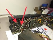
I would look closely at the 10 ohm resistors 133/233 and 145/245 on the back plate. Check it fully by testing ohms reading from base feed bare to output block. See photo attached which shows left channel positive rail check points. The solder on these 500’s are questionable at best. Also if the value moves higher you will not get the bias value is range. I know both the values 820 and 680 resistors will net a full range for adjustment. Your problem is elsewhere.
Just my thoughts
Just my thoughts
Attachments
Last edited:
grapplesaw
Veteran and General Yakker
Just want support you in fully checking this unit out. If you don’t and proceed to use it you may have further isues.
The 500’s are a tough beast to tame. Many of us have spent days on the littles problems.
I am now at the point that if it is not work after a few hours of tinkering I gut it and go full modern complimentary outputs.
The 500’s are a tough beast to tame. Many of us have spent days on the littles problems.
I am now at the point that if it is not work after a few hours of tinkering I gut it and go full modern complimentary outputs.
zeppelinofled69
New Around These Parts
- Joined
- Feb 9, 2019
- Messages
- 37
Appreciate the help Grapplesaw. I thought I had checked those resistors, but I'll open it up and check again tonight. I'll also test resistance from the solder joints instead of the resistor leads... could be that the resistor isn't making a great connection.
I certainly wouldn't mind going full modern on the amp, but I like originality (to each their own on this point) and I don't have a lot to spend. I am only into the amp for about 250 bucks at this point, so if I can get it working reliably, I can be very happy with that.
I think a lot of techs would have called it a day on this one since it works, and does stay within the spec for Bias. I just want to get it reigned in a bit to make sure it doesn't drift higher and remains reliable.
Last edited:
zeppelinofled69
New Around These Parts
- Joined
- Feb 9, 2019
- Messages
- 37
Alright... So as it turns out, I have not been measuring the Bias on the correct resistor.
Now that I am measuring voltage across the correct resistor, things are looking much better. bottom of the adjustment sits at right over 2mV DC, and I am able to dial in a 4mV Bias on the left channel.
The right channel, however, seems to continue to drift up until it hits about .5mV give or take a few tenths. Thinking the bias transistor on this one may need to be replaced.
The bias resistors in the left channel are sitting at about 9 ohms. Right channel resistors are at about 11 ohms.
Last edited:
grapplesaw
Veteran and General Yakker
I hope you mean 400mv or .4 volt
Also are you running through the dum bulb or connected to the line. You need full rail voltage to set this. As you know this is a dual rail voltage amp. And the bias changed from low to high rail. Set on high rail to no more than .4v. That will give you about .325 on low rail.
Also are you running through the dum bulb or connected to the line. You need full rail voltage to set this. As you know this is a dual rail voltage amp. And the bias changed from low to high rail. Set on high rail to no more than .4v. That will give you about .325 on low rail.
grapplesaw
Veteran and General Yakker
If dc offset is under 10 mv then that is good
grapplesaw
Veteran and General Yakker
If you get fed up with this I will help you recover your $250 you invested
zeppelinofled69
New Around These Parts
- Joined
- Feb 9, 2019
- Messages
- 37
Yes, you are correct on the .4v DC.
I am running full line voltage. I only ran on the dim bulb tester to ensure no shorts. all other testing is done at line voltage.
I have about 7mV on one channel and -3mV on the other as far as offset goes.
I am running full line voltage. I only ran on the dim bulb tester to ensure no shorts. all other testing is done at line voltage.
I have about 7mV on one channel and -3mV on the other as far as offset goes.