Hi,
I have this posted on the AK website and had a suggestion to bring it here.
I’m repairing a Phase Linear D-500 Series II amp. So far, I have replaced all electrolytic capacitors on the driver board, replaced two open diodes (1N4148 and 1N34), replaced the two 15V Zener diodes, and all out of tolerance resistors. I removed and tested all transistors on the driver board for gain and leakage and found no failed devices.
I powered up the unit and set the bias in both channels to the recommended 400mV across R145/R245.
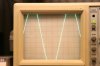
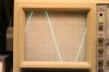
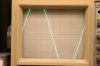
I provided a 2 kHz sine wave and checked the output of both channels on a scope while providing a 4 Ohm 250W Non-inductive load (Dale NH-250 load resistors). I pushed the unit to 200 Watts in each channel with no issue.
Next, I brought the generator up to 20 kHz and found a distortion on the negative slope of each channel. I pushed the bias up to 540 mV to get about 5 to 10ma current flowing in the emitter transistors and noticed a decrease in the distortion. The heat-sink temperature is just slightly warm to the touch at this level.
I've attached pix of the waveforms for your review. The file names on the pictures describe the test conditions.
I’m wondering if this is simply a bias level issue or am I looking at some other potential issue with this unit.
Thanks in advance,
Joe
I have this posted on the AK website and had a suggestion to bring it here.
I’m repairing a Phase Linear D-500 Series II amp. So far, I have replaced all electrolytic capacitors on the driver board, replaced two open diodes (1N4148 and 1N34), replaced the two 15V Zener diodes, and all out of tolerance resistors. I removed and tested all transistors on the driver board for gain and leakage and found no failed devices.
I powered up the unit and set the bias in both channels to the recommended 400mV across R145/R245.
I provided a 2 kHz sine wave and checked the output of both channels on a scope while providing a 4 Ohm 250W Non-inductive load (Dale NH-250 load resistors). I pushed the unit to 200 Watts in each channel with no issue.
Next, I brought the generator up to 20 kHz and found a distortion on the negative slope of each channel. I pushed the bias up to 540 mV to get about 5 to 10ma current flowing in the emitter transistors and noticed a decrease in the distortion. The heat-sink temperature is just slightly warm to the touch at this level.
I've attached pix of the waveforms for your review. The file names on the pictures describe the test conditions.
I’m wondering if this is simply a bias level issue or am I looking at some other potential issue with this unit.
Thanks in advance,
Joe