Phase Linear 400 bias, advice

Menno1000

New Around These Parts
Joined
Mar 24, 2024
Messages
9
#1
Hi All,

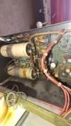
I have here my first PL 400. I got it in, checked dc output and was on channel A close to zero on channel B 14 mv. So i gave it a listen.
The amp sounded pretty nice already in this state.

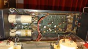
I started to swap the filter caps. One cap was down to 3000 uF. And after the swapped the caps ( to Rubycon 10000 uF) i measured the bias.
Channel A was easy to get right to 0.380 accros the 10 ohm resistor.
Channel B was really low ( 0,0 50) i could not get it any higher than .220 with bias pot turned all the way up.

Any suggestions where to start checking?
Driverboard recap? Or powertransistors?

Thanks for your help!


Menno
 

Menno1000

New Around These Parts
Joined
Mar 24, 2024
Messages
9
#6
Additional obeservations:
When i turn of the amp, channel B dies way sooner and abrupt than channel A. Also when channel A has slowly faded to crackeling silence, channel B, which was already silent, gives all of a sudden a short "tick" or blob sound.
 

MarkWComer

Veteran and General Yakker
Joined
Nov 1, 2014
Messages
3,249
Location
Gaston, SC
Tagline
Victim of the record bug since age five
#7
As it is now, if it’s showing problems, you have problems…
I wouldn’t play it any further until some upgrades are done.
 

George S.

Veteran and General Yakker
Joined
Feb 18, 2020
Messages
4,594
#9
Are the RCA jacks shorted to chassis ground?
The jacks, input and output, must be insulated from chassis ground.
The RCA's should have fiber insulating washers on both sides of the chassis hole.
The RCA's ground to the copper plate, with it's attached soldered on, ground wire.
 

Menno1000

New Around These Parts
Joined
Mar 24, 2024
Messages
9
#11
Hi all,
No luck i finding the culprit so far.

I'd like to replace my output transistors as well. I stumble across Tesla 2SD555, are these comparable with the NEC 2SD555?
Also, what kind of driver do you guys advice? I cant find any of the options mentioned in the service manual.
Thanks!
 

Gepetto

Administrator
Staff member
Joined
May 15, 2011
Messages
13,553
Location
Sterling, MA
Tagline
Old 'Arn Enthusiast
#12
Hi all,
No luck i finding the culprit so far.

I'd like to replace my output transistors as well. I stumble across Tesla 2SD555, are these comparable with the NEC 2SD555?
Also, what kind of driver do you guys advice? I cant find any of the options mentioned in the service manual.
Thanks!
DO NOT use 555s Menno. Junk by today's standards.
 

Menno1000

New Around These Parts
Joined
Mar 24, 2024
Messages
9
#16
I've been reading a lot of post her. What a great comunity! It seems i am not the only one struggling to get it right. This might be another Christine..


So it seems it is common that full comp is better than original quasi comp. What is the advantage of full comp? How does it operate differently?is there any disadvantage? I red costs somewhere? Also, red the replacement for the bias driver is a 2N5088, is that right? Or better get the original? I cant easily find that one. Only in Greece. I am in the Netherlands by the way.
 

Gepetto

Administrator
Staff member
Joined
May 15, 2011
Messages
13,553
Location
Sterling, MA
Tagline
Old 'Arn Enthusiast
#17
What is the difference between Quasi Complementary and Full Complementary?

With fully comp circuit topology, the positive half and negative half of the signal are amplified through the final current gain sections with symmetrical circuit design through the use of NPN drivers in the plus half of the signal and PNP drivers in the minus half of the signal.

The quasi comp used NPN on the plus half, like the full comp version but the minus half had the PNP driver emulated by a combination of a small PNP transistor coupled with 2 NPN pre driver and driver instead of using PNP devices. When the Phase Linear was initially introduced, this is what the designers had available to design with so they went with it.

In the last of the PL400 and PL700 production, PL did convert to fully comp on a small number before end of life of the product.

Some benefits, amp gain is more equal on the positive and negative half of the signal. In the quasi comp version, the gain of the negative side was always higher than the positive half. The global feedback compensated for this difference however and quite effectively nulled it out.

The bias settings are now extremely close for both positive and negative half. Part of this comes from the use of precision 1% resistors in the bias resistor locations, the balance comes from the symmetrical topology.

The current limit protection circuits are also now fully symmetrical leading to a more balanced onset of protection for each of the plus and minus sides.

Of course with this PL400 Backplane board, the configuration of full comp or quasi comp is easily selected by several components, jumpers and of course the choice of output drivers.

In the full comp versions, the MJ21196 (NPN) is used in the pre driver and driver positions on the plus half and the MJ21195 (PNP) is likewise used in the pre driver and driver positions on the minus half.

The use of these outstanding drivers everywhere leads to a more robust output stage as a side benefit.
 

Menno1000

New Around These Parts
Joined
Mar 24, 2024
Messages
9
#18
Thanks for your explanation!

Clear. Seems very logical.
So the the quasi comp was a workaround because the parts were not available at that time. In my (thin) audiobook simple design is often better.
What do people report as sonic differences?

Is it still easy without the backplane board but wíth the WOPL driverboard to convert to full comp?
 
Top