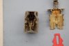
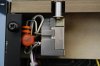
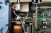
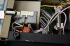
Well this thread should be short and sweet as my last three lunches have involved repairing Audio Dave's preamplifier. When Lee went for the Spec 2 that Dave was selling he mentioned that he had a Phase Linear 3000 II that stopped working so I offered to take a look at it as I really wanted to see the topology of this unit. He mentioned that is was working and just quit on him while he was poking around - with it powered up and I could see the smoke residue as shown it the photos.

You are using an out of date browser. It may not display this or other websites correctly.
You should upgrade or use an alternative browser.
You should upgrade or use an alternative browser.
Phase Linear 3000 Series II Preamplifier Repair
- Thread starter NavLinear
- Start date
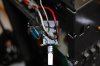
As you can see the switch area took a hit - this is the power switch and something let the smoke out. I did not figure out the culprit of this failure event but my initial visual inspection revealed the damage local to the switch. Using a multi-meter I measured the resistance across both legs of the switch and found the leg that provided power to the switched outlets on the back of the preamp to be working fine but the leg that powered up the electronics was open in both switch modes.
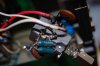
A quick explanation of how the power switch is wired. The switched outlet leg is straight forward - AC in and AC out to the four outlets located on the back of the preamp and it worked as advertised. The leg that powers up the preamplifier electronics had a 1.65k ohm resistor and 0.0027 uF cap across the input and output terminals of the power switch. When the power was off this circuit provides enough voltage to the transformer effectively providing sufficient voltage to power up the CMOS circuitry to retain the last state the preamp was in prior to power down. When the power switch was depressed (on) this provided full ac power to the transformer now providing adequate voltage to power up all of the electronics in the preamp. Well this leg was dicked up - open in both modes so something was amiss - not that one could tell from the burnt wires.
A quick explanation of how the power switch is wired. The switched outlet leg is straight forward - AC in and AC out to the four outlets located on the back of the preamp and it worked as advertised. The leg that powers up the preamplifier electronics had a 1.65k ohm resistor and 0.0027 uF cap across the input and output terminals of the power switch. When the power was off this circuit provides enough voltage to the transformer effectively providing sufficient voltage to power up the CMOS circuitry to retain the last state the preamp was in prior to power down. When the power switch was depressed (on) this provided full ac power to the transformer now providing adequate voltage to power up all of the electronics in the preamp. Well this leg was dicked up - open in both modes so something was amiss - not that one could tell from the burnt wires.
Last edited:
A bit more on the prognosis - the leg that powers up the electronics is protected with a 0.5 amp fuse (between the switch and the transformer) was intact and not stressed. No obvious shorts were measured after the switch so my assumption was that the failure mode occurred internal to the switch or with the wiring/circuitry directly attached to the switch.
What I did to isolate the problem to the switch was the following. I used a Variac to bring up the AC power to validate that nothing downstream of the switch was dicked up. On the switch leg that was open I inserted a jumper from the input and connected it to the output - then slowly brought up the voltage watching the wattage and voltage meters. All came up fine in this mode and the preamp worked as expected. I exercised the other switches to validate the preamp logic and everything worked well. I also measured the power supply voltage and input voltage to validate that the internal DC power supply was working properly.
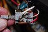
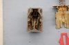
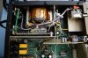
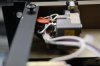
I then removed the switch from the chassis and opened it up to see what was up. What I found was one leg of the switch had somehow slipped such that it was now misaligned unable to make contact with the output terminal when the switch was depressed. In the photos notice that the left side of the switch arm is in a different position that the working right side of the switch. The outer contacts towards the bottom of the switch are where contact must be made to provide an electrical path between the input and the output terminals of the switch.
Attached are some photos of the power switch after I opened it up.
What I did to isolate the problem to the switch was the following. I used a Variac to bring up the AC power to validate that nothing downstream of the switch was dicked up. On the switch leg that was open I inserted a jumper from the input and connected it to the output - then slowly brought up the voltage watching the wattage and voltage meters. All came up fine in this mode and the preamp worked as expected. I exercised the other switches to validate the preamp logic and everything worked well. I also measured the power supply voltage and input voltage to validate that the internal DC power supply was working properly.
I then removed the switch from the chassis and opened it up to see what was up. What I found was one leg of the switch had somehow slipped such that it was now misaligned unable to make contact with the output terminal when the switch was depressed. In the photos notice that the left side of the switch arm is in a different position that the working right side of the switch. The outer contacts towards the bottom of the switch are where contact must be made to provide an electrical path between the input and the output terminals of the switch.
Attached are some photos of the power switch after I opened it up.
Attachments
Last edited:
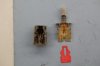
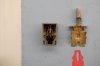
Fortunately I was able to reposition the misaligned leg of the switch and tested it using a multi-meter across both legs. The problem leg was still dicked up so I looked at the contacts under magnification and saw that the contact area was blackened. I used a burnishing tool to remove the darkened area - then I used DeoxIT-D5 to clean the contacts and then I used DeoxIT-G5 to "condition" the contacts.
This fixed the switch problem - at least at the bench level with no power applied so the next step was to reassemble it and install it back in the preamp.
This fixed the switch problem - at least at the bench level with no power applied so the next step was to reassemble it and install it back in the preamp.
Attachments
Last edited:
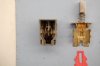
I reinstalled the switch with a new and higher wattage resistor for the CMOS circuitry and now the pre is working fine. I verified the switching logic and did a few other tests to make sure the basic functions are working as expected. This will be going back to Audio Dave next week.
Attachments
- Joined
- Jan 14, 2011
- Messages
- 75,551
- Location
- Gillette, Wyo.
- Tagline
- Halfbiass...Electron Herder and Backass Woof
A shining example of you can have too much of a good thing, too many relays, BUT!!!!!! Have never lifted a trace on a 3000 Ser II
S
sakharov
Guest
3000 series II problem
Dear Friends,
I also have a beloved 3000 series II. Recently it developed a problem. I get no output from left channel. Its not a relay problem I've replaced all relays and recap the pre amp a few months ago and it work flawlessly. Now it out puts so much current from the left channel that even warms up my headphones. Could anyone help me????
- Joined
- Jan 14, 2011
- Messages
- 75,551
- Location
- Gillette, Wyo.
- Tagline
- Halfbiass...Electron Herder and Backass Woof
Sure we can...
- Joined
- Jan 14, 2011
- Messages
- 75,551
- Location
- Gillette, Wyo.
- Tagline
- Halfbiass...Electron Herder and Backass Woof
NavLinear and Jer atr our resident experts on these things, and when we get in a bind Gepetto bails our ass out.
Oh boy - I opened one of these guys to repair and now...
Hey Sak - do you have a service manual (SM) for this? What sort of test gear do you have? How about a quick synopsis of your electronics background - that'll help us in pointing you in the right direction.
The maximum output voltage for this guy is 2 VRMS (see the SM output spec) and it normally shouldn't source an ass ton of current so something is amiss.
Is English a second language?
Nav
Last edited:
- Joined
- Jan 14, 2011
- Messages
- 75,551
- Location
- Gillette, Wyo.
- Tagline
- Halfbiass...Electron Herder and Backass Woof
sakharov, first you say you had no output on the left channel, now you have too much. Was the no left channel the condition when you bought it and the "too much" condition now??