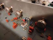
Phase Linear 2000 PREAMPLIFIER SUPER UPGRADE AND REPAIR

George S.

Veteran and General Yakker
Joined
Feb 18, 2020
Messages
5,033
#21
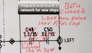
George, those are two, polar electrolytics in a bipolar configuration, at each channels output. We've replaced each pair with a single Panasonic polypropylene film cap. The value escapes me at the moment as I'm working.
Keep up the good work!
 

GeorgeP

Journeyman
Joined
Mar 22, 2023
Messages
107
#22
Yes, I'm doing that next. The one slot will be for the resistor, the other for the film cap. It works out perfect.
The sound quality with the chip upgrade is a definite plus! Especially the upper midrange to sibalences ...very well defined and transparent and flat as a pancake to 30 kHz +.
Lets face it...the original chip is the first 741 op amp with the compensation, packaged quad. Great for the times, but the newer chips are distortion less. and vey broadband...Just needed to be tamed a bit. The new smaller packaged part was quite warm, so I epoxied a small metal L-Bracket to them to move some heat away. Worked out nice. I'll post a pic of that next go-round, maybe this weekend. electrolytic change and resistor added.jpg
 
Last edited:

George S.

Veteran and General Yakker
Joined
Feb 18, 2020
Messages
5,033
#23
Additionally, the RCA ground trace is separated between the inputs and outputs, with each grounded with it's own screw to the chassis.
In addition to going to a single film cap at the outputs, Joe suggested bridging that gap with wire, and insulating that far right screw from ground, so there is no inherent ground loop.
I bridged that gap with solid strand copper, then carefully chamfered the copper away from the far right screw with a bit, then put a nylon washer under the screw head.
This way the preamp has one and only one ground, the screw on the far left by the transformer.
Thanks again Joe!
 

grapplesaw

Veteran and General Yakker
Joined
Aug 13, 2014
Messages
2,777
Location
Vancouver
Tagline
---
#24
Yes, I'm doing that next. The one slot will be for the resistor, the other for the film cap. It works out perfect.
The sound quality with the chip upgrade is a definite plus! Especially the upper midrange to sibalences ...very well defined and transparent and flat as a pancake to 30 kHz +.
Lets face it...the original chip is the first 741 op amp with the compensation, packaged quad. Great for the times, but the newer chips are distortion less. and vey broadband...Just needed to be tamed a bit. The new smaller packaged part was quite warm, so I epoxied a small metal L-Bracket to them to move some heat away. Worked out nice. I'll post a pic of that next go-round, maybe this weekend. View attachment 76758
I’d sure like to see this run through some test gear. Kind of goes against the grain and your hearing may be a lot different than mine. Larger cap on the output is usually better dynamic not smaller one. The resistor is only a dampener of sorts . You can find Joe had done a good write up on capacitance in output section of preamps. It is somewhere in a post from the past year.
 

GeorgeP

Journeyman
Joined
Mar 22, 2023
Messages
107
#26
I’d sure like to see this run through some test gear. Kind of goes against the grain and your hearing may be a lot different than mine. Larger cap on the output is usually better dynamic not smaller one. The resistor is only a dampener of sorts . You can find Joe had done a good write up on capacitance in output section of preamps. It is somewhere in a post from the past year.
I took the 1uF approach to start, since the PL2000 is two 2.2uF in series = 1.1 uF)....its 16K ohms at 10Hz. Yea...that's about 10 dB down, and only 1dB at 100 Hz. Maybe 4.7uF is a bit better for the punch feel! This assumes 50K AMP input Z. I use 4.7uF at all amp inputs to block DC. I'll put the 4.7 uF there in the 2000. The resistor actually prevents the 16KHz stability issue... with loads from 50K to 1K...now Clean. I initially saw the sinewave at 16KHz at 1V with NO input signal, that surprised me. The Tone controls have a "Zero pole" around there so the resistor is required (50 to 100 Ohms). The spec sheet for the chip mentions this stability with capacitive loading, since it is a 35MHz chip. Maybe I'll run some tests on the bench with this and the PL400 just upgraded (input DC blocked with 4.7uF). TBD. I had to many DC amps destroy speakers when they failed in the past.
 

kangal

New Around These Parts
Joined
Apr 13, 2022
Messages
8
Location
Roseville, California
#27
Great job on your build GeorgeP. I just came across one of these PL2000, it does have a small issue. Right channel is very low in stereo mode, ok when switched to mono.
Any hints of what could be causing this issue? I plan to replace all caps and maybe attack some of the mods you guys have done on these.
Also, where can I get the service manual?
Thanks

Hugo
 

GeorgeP

Journeyman
Joined
Mar 22, 2023
Messages
107
#28
Great job on your build GeorgeP. I just came across one of these PL2000, it does have a small issue. Right channel is very low in stereo mode, ok when switched to mono.
Any hints of what could be causing this issue? I plan to replace all caps and maybe attack some of the mods you guys have done on these.
Also, where can I get the service manual?
Thanks

Hugo
Looks like all output gain stages good. I bet its the right input connector, if using a high level input...maybe the mating connector pin is to long shorting the input to ground. Or, if your talking about the turntable inputs, the phono input, maybe that first high gain stage is busted.
If you have a scope, its easy to see.
 

kangal

New Around These Parts
Joined
Apr 13, 2022
Messages
8
Location
Roseville, California
#29
I am using a CD player and have connected into the Aux, Tuner and Tape 1 inputs with same results. I do not have a scope but will start making some measurements with a DVM.
 

George S.

Veteran and General Yakker
Joined
Feb 18, 2020
Messages
5,033
#30
The original pots all need rebuilt at this point due to age. The CTS branded balance and volume pots have quality silver plated wiper slip rings that have deposits that no amount of DeoxIT spray will remove.
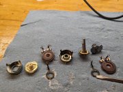
Here's the balance pot with the screwdriver pointing to the tarnished slip ring. I carefully polish the slip ring clean, clean all with alcohol, lightly grease the carbon tracks, wiper contacts, barrel and shaft, with DeoxIT grease.
Keep the balance carbon tracks in correct order as they're logarithmic and reversed value from each other.
I've had very good results rebuilding the balance pots and all the other pots in the PL2000. The CTS pots are worth rebuilding and not replacing. The tone pots are Alps brand and also get the same treatment.
The CTS volume pot gets rebuilt in a similar manner. I started experimenting last winter by subbing in a ladder type stepped attenuator for it. Initial results were excellent. Just got very busy this summer and haven't got time to revisit the preamps.
The second photo shows clean slip rings and wiper contacts. Don't scratch that silver plating! I use a well worn Dremel steel rotary brush, carefully.
 

Attachments

George S.

Veteran and General Yakker
Joined
Feb 18, 2020
Messages
5,033
#31
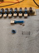
Oh, and the input selector switch is also a silver plated CTS (also used in the Acurus L10). It gets the same treatment, but mark the parts with a sharpie and photo beforehand for correct reassembly. The plastic dust guards pop out for easy service of the contacts.
 

George S.

Veteran and General Yakker
Joined
Feb 18, 2020
Messages
5,033
#33
Yup, recap and rebuild all the pots and switches is critical step one. The Alps push button switches are easy to open and clean, then lightly grease. Once open, you'll see the contacts. Wet some coffee filter paper strips with DeoxIT and pull them through the sliding contacts. And use wetted Q'tips on the inside contacts.
And get that spray residue off the boards and pots. The Alps tone pots phenolic tabs on one of my preamps were degraded and weak from whatever a prior owner sprayed. I suspect WD40!
 

Attachments

mlucitt

Veteran and General Yakker
Joined
Jun 24, 2011
Messages
3,479
Location
Jacksonville, FL
#36
Maybe I'll run some tests on the bench with this and the PL400 just upgraded (input DC blocked with 4.7uF).
I used a 22uF 63V 10% TDK Film (Polyethylene Terephthalate) on each output channel, Mouser P/N 871-B32523R226K because Joe said the more uF, the better in this application. I chose film capacitors because electrolytic capacitors in the sound path are not optimal.
I thought it prudent to add a 4.7M 1/4W resistor on each capacitor to ground, to bleed any DC.

Unfortunately, the PL2000 (not Series II) did not use the ALPS controls, but the ones I have in my PL2000 did clean up rather well.

Also, if you want to reduce the noise floor even more, try adding .1uF film capacitors across the supply legs of the OPAMPs.

OPAMP Bypass .1uF 63V Cap.jpg
 

GeorgeP

Journeyman
Joined
Mar 22, 2023
Messages
107
#38
Gents,
I liked the way mine turned out. Sounds extremely clean. The bass and treble controls are very nice only responding to the extreme audible Range for "SPEAKER" RESPONCE BOOSTING. I like it so much, I decided to lay out a brand-new version of it with the best op-amps ever, and surface mounted components.
The dual 1602 op-amp is good to 35MHz...super low distortion of .00003%...totally unmeasurable.
I attached the new PCB layout, and schematic. It is NOT intended to go into the old chassis, as I don't like the slide switches and additional inputs that degrade the signal path. I used one switch to go between the Phono and the one line input. Want more inputs...then using an external source selector box is needed. I added local regulators, and an option for a 80KHZ switching supply to avoid transformer hum as an option to try (not on schematic yet). I also added RF suppression to attenuate signals over 1 MHz, since the op-amps will respond to any RF on the input connectors from ham operators / police or CB operators. I'm going to order 3 PCBs to start and see how well it performs. I did keep the "AMBIENCE" circuit also...nice! All analog ground, chassis shield, and power supply returns are separated, then brought to one common point as per good RF /audio design. If it turns out good as expected... I'll order boards for any of you that want to build it, I may even do a total kit with parts. Winter is coming...a nice project? The prints are Tabloid if you want to take a close look.
 

Attachments

J!m

Veteran and General Yakker
Joined
Dec 24, 2019
Messages
10,831
Location
Connecticut
Tagline
BOT
#39
This looks interesting.

I was working with Wyn Palmer on a parallel opamp balanced line preamplifier. He elected to not pursue the project, so it never went beyond a specification sheet (and front panel design) for me. His phono pre is legendary and the headphone amp, once I went to a stepped attenuator, is fantastic. He's a member here, and I'd love to hear his feedback on your design as I am no electrical designer.

Your measured distortion number is impressive!

I don't think this could be made to operate with a balanced line, but maybe it can (with rework)... what do you think?
 

GeorgeP

Journeyman
Joined
Mar 22, 2023
Messages
107
#40
This looks interesting.

I was working with Wyn Palmer on a parallel opamp balanced line preamplifier. He elected to not pursue the project, so it never went beyond a specification sheet (and front panel design) for me. His phono pre is legendary and the headphone amp, once I went to a stepped attenuator, is fantastic. He's a member here, and I'd love to hear his feedback on your design as I am no electrical designer.

Your measured distortion number is impressive!

I don't think this could be made to operate with a balanced line, but maybe it can (with rework)... what do you think?
I dont see why not...its just an op-amp. Set it up using both + & - inputs...a typical differential amplifier design. Breadboard it an try it?
 
Top