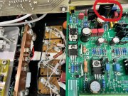
Nice 400-ll to rebuild

Glen, nice work with that Zener diode addition. I don't see a downside (i.e. noisy diode switching or heat generation) and the rating of the 1N5366 diode is 5 Watts, .....Thanks, Mark

It's funny you mentioned switching noise. When I looked at the dwg. the first thought I had would be to hang a .1uf cap on the anode of the zener or the regulator output. No justification, but I'm always concerned about oscillations etc.
 
It's funny you mentioned switching noise. When I looked at the dwg. the first thought I had would be to hang a .1uf cap on the anode of the zener or the regulator output. No justification, but I'm always concerned about oscillations etc.
Don there is a .1 uf cap right after the regulator along with a 220 uf audio grade electrolytic cap. There is no oscillations of any concern.
 
I spied another possible mod to the WOA Rev G1 Control Board. What capacitor are you using for C4L and C4R? They do not look like the Nichicon MUSE 470uF/25V capacitors that I have been using.
 
I spied another possible mod to the WOA Rev G1 Control Board. What capacitor are you using for C4L and C4R? They do not look like the Nichicon MUSE 470uF/25V capacitors that I have been using.
Mark they are what came from Joe so not change on my sideIMG_4095.png
 
The only other item on the board is two .33 Panasonic metal film caps on the 12 and 11 pin in for both channels.

IMG_6961.png
 
Mark they are what came from Joe so not change on my side
Glen,
I see now that it was probably just the light angle in the picture.
Dark Cap Circled.jpg

The .33uF Panasonic metal film caps on the 12 and 11 pin in for both channels is a good idea for an amplifier that does not have the WOA Backplane Boards installed. The PL400 Backplane Boards have 7.5uF of capacitance across the rails on each channel.
I see that you also have installed four of those 1.5uF Panasonic capacitors on the chassis for each channel. That is a lot of rail capacitance!
 
Last edited:
So having been up to the lake house and repairing my boiler I set down to test this new amp

well had some issues with putting a ground wire on the wrong pin on the balanced to unbalanced board but that is sorted

first the soft start does what I wanted only 4-5 amps to start up
Wish I could post a video but that is a feat I have yet to master

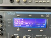
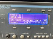
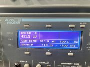
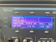
also residual noise is good enough at .5mv on the balanced inputs, not sure how to short a balanced input so did not get that
The amp noise is less with inputs on the board shorted Noise is 320uv
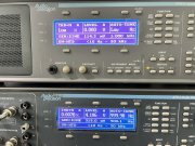
The distortion is excellent and shown at 1-1/2watts output IMG_7035.jpegIMG_7034.jpegIMG_7033.jpegIMG_7032.jpeg
And I am happyIMG_7045.png
 
Last edited:
Was my mind in in the game today
Retested with a 8 ohm load
Thought distortion was way to low

floor noise improved withis load attached

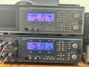
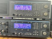
I had to use the top AP to generate balanced output , because it’s a balanced setup machine and read the amp out put on the bottom APIMG_7040.jpegIMG_7039.jpegIMG_7036.jpegIMG_7037.jpeg
 
Back
Top