
You are using an out of date browser. It may not display this or other websites correctly.
You should upgrade or use an alternative browser.
You should upgrade or use an alternative browser.
New PL 400 Series II build
- Thread starter Wombat
- Start date
Double check your using the correct outputs at the correct location per the documentation Joe sent.
Also notice the pins are offset, as also are the holes in the heatsinks. They'll push all the way in against the silpad with the magnet. Don't use the screws to seat them. Think your overlooking something basic.
Also notice the pins are offset, as also are the holes in the heatsinks. They'll push all the way in against the silpad with the magnet. Don't use the screws to seat them. Think your overlooking something basic.
Wombat
New Around These Parts
- Joined
- Mar 31, 2023
- Messages
- 41
That's what I initially thought. Know there are offset. Have printed chart of what goes where. . Can see the gold cups centered at each location. Tried using my old SO3 sockets as suggested for alignment. Filed off the ends of one transistor's pins to taper it a bit. Unless the transistor pins are just too big, I'm stumped. Time for a frosty cold adult beverage and the 4th!
Wombat
New Around These Parts
- Joined
- Mar 31, 2023
- Messages
- 41
Transistors: The Sequel. The one on the left in the pictures is a MJ15024G. Right is the MJ21196G. MJ15024G will go in wherever I want. None of the MJ21196G's or 95G's will go in anywhere. I am ordering a couple from Mouser to see if maybe it is a production run issue. Failing that, I am left with:
1. Aliens
2. Demonic possession.
1. Aliens
2. Demonic possession.
Attachments
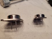
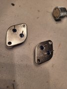
3. burrs or blunt on the ends of the transistor leadsTransistors: The Sequel. The one on the left in the pictures is a MJ15024G. Right is the MJ21196G. MJ15024G will go in wherever I want. None of the MJ21196G's or 95G's will go in anywhere. I am ordering a couple from Mouser to see if maybe it is a production run issue. Failing that, I am left with:
1. Aliens
2. Demonic possession.
JEDEC controls all aspects of defined packaging. The JEDEC lead diameter spec is 0.038-0.043. Most all ON devices fall at 0.040" diameter.
JEDEC does not control if there is a burr or blunt at the end of the leads from cutoff operations.
AngrySailor
Veteran and General Yakker
- Joined
- Oct 15, 2014
- Messages
- 3,419
- Tagline
- ---not quite right
Heat sinks on upside down? Can’t remember if that was the 400/1 or 700/1 where it was possible to mount the heat sinks upside down or backwards and nothing lined up... you shouldn’t have to pull them in with the screws, they go in all the way with the magnetic holder and gentle pressure when lined up... it goes quick once you get the feel of it.
mlucitt
Veteran and General Yakker
Don is in Spokane, WA. Anyone here nearby that could look over Don's shoulder as he is trying to seat some uncooperative Output Transistors?
I would drive over there but it is 2,820 miles, one way.
I would drive over there but it is 2,820 miles, one way.
wattsabundant
Chief Journeyman
I have been to the point of filing the tips to a sharper point sometimes. On my later builds I will test fit to each specific location while the backplane are still on the bench. Then number them and keep them in order until its time..
Same here. I check the pins to make sure they are straight and then proceed with Lee's technique. It works.
Wombat
New Around These Parts
- Joined
- Mar 31, 2023
- Messages
- 41
Filed, and traightened with old TO 3 socket. Heat sinks on correctly. Probably not going to take things apart to hand match transistors to sockets. Awaiting two more from Mouser. Meanwhile, I have two sets of shielded twisted pair wires from the RCA jacks and the pots. To the board are red and white wires - right channel. Red is signal, white is shield. Left channel has a solid black wire and a black wire with writing on it. Which is the signal and which is the shield? As always, thanks for the help!
Looking at the pots, you'll see 3 solder lugs. The center lug is called the wiper. The wiper always gets the wire to the control board signal connection.
So that leaves the two outer lugs. One gets signal from the RCA, and the other gets the grounds from the twisted pair.
How you wire the outer lugs determines high resistance (low volume), or low resistance (high volume) when the pot is at extremes.
You may want to ground one end of the shield, or not, but not both ends I think, as it may produce a ground loop. I don't know, I use Belden coax here. Hopefully someone who uses STP can comment.
And, I don't use attenuator pots in my 3 WOPLs. Build them the way you want, but the difference in the treble on my JBL Millenniums was very apparent right away.
Getting the attenuator pots out of the amps, and going with a 24 step Dale resistor attenuator for volume in the preamp has made a huge difference in sound quality.
Getting the attenuator pots out of the amps, and going with a 24 step Dale resistor attenuator for volume in the preamp has made a huge difference in sound quality.
Wombat
New Around These Parts
- Joined
- Mar 31, 2023
- Messages
- 41
Thanks for the information. I am not smart enough to figure out how to re-wire the pots to the RCA ground plane, then to the R 1 and L 1 PCB board inputs with coax. I have seen the pros and cons about removing the pots. Both of mine are new. Seems like running the amp at full output if you have a pre-amp that puts out 2 volts might not be a good choice. The manual says the 400 needs only one volt to bring it to full power - but I am no where close to knowing what I am talking about.
Wiring pots confused the hell out of me until the guys here helped me understand.
Rule #1 is, wiper is signal to control board.
Rule #2 is, signal from RCA goes to a outside lug, and the two grounds go to the other.
Rule #3 is, the outside lug connections determine if volume increases or decreases while turning the pot right or left.
Therefore, you can wire it conventional with highest volume when pot is turned far right, or reverse the outside lug connections and highest volume is pot turned far left.
This is true with linear taper pots. If you have logarithmic, more examination of the pot with a ohm meter is required.
Rebuilding logarithmic pots has confused me more than once.
You'll get it. Just takes practice and doing it. Use your ohm meter to sort it out.
Last edited:
Wombat
New Around These Parts
- Joined
- Mar 31, 2023
- Messages
- 41
Transistor update. Got my torque screwdriver back so I thought I would take another whack at this. Actually got some in. Additional items needed:
A. One(1) bottle of your favorite isopropyl cleaning alcohol (or 12 year old scotch);
B. One (1) shot glass; and
C. Sixteen (16) new swear words that will scare your dog.
Fold down PCB. Take shot. Loosen bias "P" brackets and stand offs very slightly. Take shot. Loosen upper back plane screws and stand offs very slightly. Take shot. Put amp face down. Put transistor on magnetic holder. Take shot. Wiggle, push, wiggle, wiggle, push, wiggle, use new swear word. Secure with screws. Take shot, Repeat.
Seriously, thanks to all who have tried to help with this vexing (to me) process.
Vintage 700b
Chief Journeyman
I don't remember that procedure in Joe's protocol, but hey, it will get something done!Transistor update. Got my torque screwdriver back so I thought I would take another whack at this. Actually got some in. Additional items needed:
A. One(1) bottle of your favorite isopropyl cleaning alcohol (or 12 year old scotch);
B. One (1) shot glass; and
C. Sixteen (16) new swear words that will scare your dog.
Fold down PCB. Take shot. Loosen bias "P" brackets and stand offs very slightly. Take shot. Loosen upper back plane screws and stand offs very slightly. Take shot. Put amp face down. Put transistor on magnetic holder. Take shot. Wiggle, push, wiggle, wiggle, push, wiggle, use new swear word. Secure with screws. Take shot, Repeat.
Seriously, thanks to all who have tried to help with this vexing (to me) process.
Glad it is going well for you now. Yes, 16 swear words that will scare your dog, and a lot of wiggling and pushing.....you've got it!
