New Member, New Project, Here's my 400!

Northwinds

Veteran and General Yakker
Joined
Mar 18, 2013
Messages
7,566
Location
Coventry, CT
Tagline
Fondler errrr... fan of all Nav's avatars
#21
And I feel like a snob always looking down at you. Lol.

But seriously, going to Ron's house is like going to a flea market of all audio goodness. He takes all my money. Big jerk.
Bwahahahahhahahahahaaaaa!!!!! I hook you up righteous though
 
Joined
Feb 4, 2016
Messages
94
Tagline
---
#23
I figured since the visual inspection didn't throw up and red flags, it was time to take the next step. So, out came the dim bulb tester with a 150 watt bulb. Flicked the switch and as desired, the bulb was bright for less than a second and the front panel lights both worked too. Sweet. Removed DBT and plugged in directly. No smoke. Measured mV across speaker jacks. Left side had 20mV and right side had 15mV. After about 30 seconds, the left side went to zero and the right side to about 7mV. So I would call those good results.

Guess it's time to hook up a pre and put some power to it.
 
Joined
Feb 4, 2016
Messages
94
Tagline
---
#28
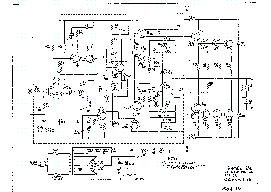
Ok, here's my next stupid question...can somebody point me to a thread or photo showing me the location of the R38/R39 resistors I'm supposed to be measuring across? I downloaded the service manual telling me the procedure, but the location diagrams are hard to read.
 

Northwinds

Veteran and General Yakker
Joined
Mar 18, 2013
Messages
7,566
Location
Coventry, CT
Tagline
Fondler errrr... fan of all Nav's avatars
#29
No question is stupid when dealing with these amps Dan, one slip and massive damage can ensue, looks like middle right in the below diagram which for some reason looks smaller when I posted it (this is provided the 8 fin is set up the same as this 1973 diagram)

 
Last edited:
Joined
Feb 4, 2016
Messages
94
Tagline
---
#31
Dan, is your control board a PL_14?
Back of the board does have a 14 on it, so I'm gonna say yes.

I'm assuming the two orange/red colored adjustable pots are used to set the bias. Just unclear where I'm suposed to measure.

Sorry I don't have the working knowledge on the locations and variations of these things. Bare with me guys, I'll catch on.
 

laatsch55

Administrator,
Staff member
Joined
Jan 14, 2011
Messages
75,195
Location
Gillette, Wyo.
Tagline
Halfbiass...Electron Herder and Backass Woof
#32
R38/39 are the 10 ohm resistors on the backwall between the base bus bar and the emitter resistor common tie point( or the output)....
 
Joined
Feb 4, 2016
Messages
94
Tagline
---
#33
Thank you both. So these, correct?

That's what I used to check at least. I actually checked at all 4 banks even though they are obviously adjusted in pairs. Here's what I have after letting it run for 20 minutes or so at idle (I did adjust them down a little). Starting at the bank closest to the jacks...

1) 347 mV
2) 376 mV
3) 372 mV
4) 360 mV

20160207_153326.jpg
 
Last edited:

laatsch55

Administrator,
Staff member
Joined
Jan 14, 2011
Messages
75,195
Location
Gillette, Wyo.
Tagline
Halfbiass...Electron Herder and Backass Woof
#35
Adjust to the Positive rails. Then just check the negative. 10% difference between positive and negative drives is acceptable....
 
Joined
Feb 4, 2016
Messages
94
Tagline
---
#37
Yeah, I tweaked them a little more, but they are pretty close to the numbers I posted before. Later this week I will hook it up and test it out. Perhaps with Stuarts NAD preamp.

Then it will be time to order some parts...
 

Northwinds

Veteran and General Yakker
Joined
Mar 18, 2013
Messages
7,566
Location
Coventry, CT
Tagline
Fondler errrr... fan of all Nav's avatars
#38
What is it a NAD 1020? I sold mine last year, they are pretty decent preamps
 
Top