porkchop61
New Around These Parts
Hi all. Happy New Year.
First post here, but long time lurker.
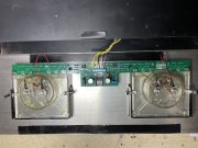
I have an early 4 fin 400 that I’m replacing the meter lamp board with a new White Oak LED board.
The existing factory board meter lead solder pads are etched with a “+” on the PCB, but the lead goes to the meter on the non-positive
terminal. Both meters are wired this way, and the meters function correctly. (I say non-positive terminal because the meters only have a “+” mark)
I’m asking because when I install the new LED light board, do I wire the positive lead to the non-positive terminal, or wire it as marked?
I don’t want to ruin a new PCB, or smoke the unobtainium meters.
Has anyone else seen this on an early 4 fin 400?
Thanks
Glenn


