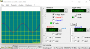
Head azimuth

Alex SE

Journeyman
Joined
Oct 10, 2021
Messages
251
Location
Sweden
Tagline
Amateur
#1

Alex SE

Journeyman
Joined
Oct 10, 2021
Messages
251
Location
Sweden
Tagline
Amateur
#2
Have replaced a roller and re-adjusted azimuth a little and now its maybe a little more steady but those jump from time to time are still present (cant tell if more, less or the same). Or that have something to do with measuring itself, not with a deck?!
At least a channels are almost equal and azimuth looks fine.
1674309316300.png
 
Last edited:

A.N.T.

Journeyman
Joined
Aug 21, 2021
Messages
55
Location
Cheshire UK
Tagline
Femtoamp- Volt- and Tape- nut.
#3
From the first video, it looks like the scope program loses synchronisation (green light blinks) and it looks like a “jump”. It is not real.

Cheers

Alex
 

George S.

Veteran and General Yakker
Joined
Feb 18, 2020
Messages
4,590
#4
Joe's #1 rule."It's your test equipment (causing the issue)". Found this to be so true so many times!
I never could get a Focusrite Scarlet to work correctly with audio testing software. Best I found was a Asus U7. Worked alright. But one can buy a good used scope for a little more than the cost of a U7.
Maybe try testing each channel separately?
 
Last edited:

Alex SE

Journeyman
Joined
Oct 10, 2021
Messages
251
Location
Sweden
Tagline
Amateur
#5
From the first video, it looks like the scope program loses synchronisation (green light blinks) and it looks like a “jump”. It is not real.

Cheers

Alex
First of all, i have to say that IT'S REALLY GREAT TO SEE YOU here Alex. It was a long time ago, hope everything is fine with you.
Are you working on something new? You know that people like to read about your new projects and discoveries.

About "the problem", I didn't knew about that green "lamp". In that case everything seems to be in order. It's obvious that, as you said, not many decks can hold azimuth steady.
Just curious, which roller causes unsteady azimuth? Left, the smaller one or right, a bigger one? Or is it something else?
 

Alex SE

Journeyman
Joined
Oct 10, 2021
Messages
251
Location
Sweden
Tagline
Amateur
#6
Joe's #1 rule."It's your test equipment (causing the issue)". Found this to be so true so many times!
I never could get a Focusrite Scarlet to work correctly with audio testing software. Best I found was a Asus U7. Worked alright. But one can buy a good used scope for a little more than the cost of a U7.
Maybe try testing each channel separately?
I'm actually not so sure that software can be as good as a real stuff unless the one really know how to adjust/calibrate everything and then use devices compatible with software.
My ex sound card was some external Creative card. Working pretty nice, but I had some problems with AudioTester (roll off under about 400Hz. Sold it and bought Scarlet which, believe or not, have the same problem. Then I've discovered, roll off is present only when a card is fed with -20db signal. The closer a signal is to 0db, a signal is more and more flat. Don't remember on how many db it is totally flat. Seems that standard sound cards are not made for a low input/output signals.
Only thing I'm missing with scarlet is no optical in/out, but for that price I can live with that. Using a Sony MD as a converter.
 
Joined
Mar 6, 2022
Messages
359
Location
Minnesota
Tagline
Always Thinking Outside The Box.
#7
I'm having the same problem, have you tried the scope setting in XY mode? which shows a 2 45 degree lines
Right now I'm working on getting the wow and flutter down first and started out about .22 and had spikes every now and than , now I got it to about .05 , .045 (w software reading the din ave 10 seconds) but still has a spike so I will be changing the pot in the caption motor and still be waiting for new parts and I thinking the pots are old and sensitive to vibrations.
What's your wow and flutter at?
 

Alex SE

Journeyman
Joined
Oct 10, 2021
Messages
251
Location
Sweden
Tagline
Amateur
#8
I'm having the same problem, have you tried the scope setting in XY mode? which shows a 2 45 degree lines
No, I didn't.

Right now I'm working on getting the wow and flutter down first and started out about .22 and had spikes every now and than , now I got it to about .05 , .045 (w software reading the din ave 10 seconds) but still has a spike so I will be changing the pot in the caption motor and still be waiting for new parts and I thinking the pots are old and sensitive to vibrations.
What's your wow and flutter at?
Haven't checked yet. Actually I didn't touched a deck after posting here. Last thing I did was replacing a left pinch roller (right one have no more than 30 working hours).

There are a couple things I have to do with that deck and I feel so tired these days that I just don't feel myself to go into all of that. Travelling next Sunday for 4 days and will probably continue working on that deck weekend after.

1. Have to do a PB response test (thanx Vince for advice), and probably replace head grounding resistors 68K to 100K (?).
2. Make a list and order some caps, resistors and some Bourns 3296 trimpots. Put them in a deck :)
3. Re-check & if needed re-adjust Pb level, output level and peak meters
4. Adjust bias and replace 2 resistors in REC section.
5. At the end adjust Cal.

Cant even think about all that.
 
Joined
Mar 6, 2022
Messages
359
Location
Minnesota
Tagline
Always Thinking Outside The Box.
#10
No, I didn't.
Haven't checked yet. Actually I didn't touched a deck after posting here. Last thing I did was replacing a left pinch roller (right one have no more than 30 working hours).
There are a couple things I have to do with that deck and I feel so tired these days that I just don't feel myself to go into all of that. Travelling next Sunday for 4 days and will probably continue working on that deck weekend after.
1. Have to do a PB response test (thanx Vince for advice), and probably replace head grounding resistors 68K to 100K (?).
2. Make a list and order some caps, resistors and some Bourns 3296 trimpots. Put them in a deck :)
3. Re-check & if needed re-adjust Pb level, output level and peak meters
4. Adjust bias and replace 2 resistors in REC section.
5. At the end adjust Cal.
Cant even think about all that.
I finding that restoring Cassette Decks are very time consuming and also take up a lot of room.
replacing the belts and getting it back running is easier to do but restoring as I'm founding out is a lot of detailed working and Precision work and detail for looking at each part as a individual.
The software I use Thanks to A.N.T Audio for the downloading link to test Wow & Flutter is
WFGUI program by Alex Freed
http://www.ant-audio.co.uk/index.php?cat=post&qry=library
You also need a Calibrated test tape 3000 or 3150Hz and Azimuth some use 400hz to 10kHz the higher the more accurate, which you probaley already have for testing.
And one cable, a 3.5 from commuter to the output from Rca Tape cassette.

Currently recapping mine w a kit I bought from E-bay (it took 3-months and tons of emails to get all the parts) and he also sent some wrong parts.
he also sent a lot of 22uf BP capacitors to replace the 22uf electronic capacitors
it does not seem right to me? (thought it was 4.7uf or less?) and is BOM documentation does not show most of them as BP.
 

vince666

Chief Journeyman
Joined
May 15, 2013
Messages
979
Location
deep south of Italy
Tagline
I will not be missed! :p
#11
Currently recapping mine w a kit I bought from E-bay (it took 3-months and tons of emails to get all the parts) and he also sent some wrong parts.
he also sent a lot of 22uf BP capacitors to replace the 22uf electronic capacitors
it does not seem right to me? (thought it was 4.7uf or less?) and is BOM documentation does not show most of them as BP.
replacing polarized electrolytic capacitors with non polarized ones is always possible, 'cause the non polarized can do the work the polarized do in both ways.
But if they are in the signal path it's a good choice to put non polarized ones, then they can easily do a better work.
I mean those ones which are, i.e., connected in series with the signal so that the (AC) signal goes through them.
While, the electrolytic capacitors which handle power supply / filtering purposes can happily stay polarized because they are always well biased as they are connected to ground on one end while they are subjected to some (positive or negative) DC voltage on the other end.

Of course, giving a good look at the schematic will tell you where you may take some advantage in putting non polarized ones and where a polarized one is just the way to go.

Not being too expert, I am not sure if i described the situation the most proper way.... hopefully someone more expert will chime in and correct me or explain it better than I did.
 

nakdoc

Chief Journeyman
Joined
May 11, 2011
Messages
619
Location
Nashville, TN Music City
Tagline
highly biased
#12
Always play music and listen to your deck before, during, and after testing. A drop out problem like the OP describes is easily tracked down by playing music. If the music plays fine, then it is the test set up. Azimuth is easily judged by putting your monitor amp into MONO (you need speakers, not headphones to judge).
Any repetitive wow glitch is caused by something rotating. A non-synchronous spike is usually a measurement artifact and should not be a cause for action. Inside the test equipment, the playback tone is compared to an internal reference tone, with a filtered and weighted difference voltage being sent to the meter. When plyback drops out, even for an almost inaudible moment, the difference signal is at maximum, so you see and hear (if you can listen to the W&F filter output) as a big spike.
For a good time, measure your wow and flutter, then bang on the table, the top of the deck, back of the deck, etc. and enjoy the spike show.
 
Joined
Mar 6, 2022
Messages
359
Location
Minnesota
Tagline
Always Thinking Outside The Box.
#13
Vince, Thanks
I will have to look at all the capacitors in the Auide path than See were the 22uf are in the drawings. Because it's the MB it takes a lot zooming in but I will look at it.
Nakdoc
Thanks I will have to get back to this. I will try that some of them tricks.
The spike seem to be random so I hope when I get my new 10 turn pot will fix it since the pot are located in the motor which has a some vibration and they are hard to adjust (like all the old desks) so I think their just loose and worn out. :)
 

WOPL Sniffer

Veteran and General Yakker
Joined
Aug 10, 2015
Messages
11,230
Location
Minnie-Soda
Tagline
Screw it
#16
Vince, Thanks
I will have to look at all the capacitors in the Auide path than See were the 22uf are in the drawings. Because it's the MB it takes a lot zooming in but I will look at it.
Nakdoc
Thanks I will have to get back to this. I will try that some of them tricks.
The spike seem to be random so I hope when I get my new 10 turn pot will fix it since the pot are located in the motor which has a some vibration and they are hard to adjust (like all the old desks) so I think their just loose and worn out. :)

Steve, I don't get it..... "Like all the old Desks"?????
 
Top