Goldpoint Stepped Attenuators

mlucitt

Veteran and General Yakker
Joined
Jun 24, 2011
Messages
3,479
Location
Jacksonville, FL
#1
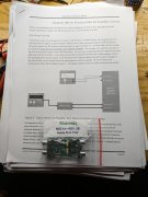
This is a picture of my bench "Mule" Full Complementary PL400 "WOPL" amplifier which I use to test newly assembled WOA Rev G1 Control Boards for customers. Yes, the wiring is long because I need to drop the Faceplate twice per test and sometimes I test two or three boards in one session. Also, note the large Series X 440VAC Line-to-Neutral Safety Capacitors I installed before Joe created his Bridge Rectifier Snubber Board.

In any case, a previous owner drilled a single hole in the otherwise nice Faceplate for a potentiometer. I deleted the Chinese potentiometer when I upgraded the amplifier to Full Complementary operation. The resulting hole bugged me, so I installed a double layer potentiometer because I like to have the input test signal low at Power On with an untested Control Board in place for the first time; my HP 3311A Function Generator is preset to 1.0V RMS and I don't like to turn it down and then recalibrate it every time I test a Control Board.
The 100K dual potentiometer was one I had in my parts drawer and it ended up being unequal from Channel A to Channel B, like the wafers were not "timed" or tracking correctly. This bugged me even more than a blank hole in the Faceplate.
So I searched for "Audiophile Quality" potentiometers (there are many from China). There are inexpensive resistor chain types, which just add more resistors in series to get the input signal down low and each resistor adds some noise. There are Ladder types, which only have two resistors in circuit at once. There are Shunt types, which only use two resistors but change the load impedance as you turn the control.
I finally selected the 24 position Goldpoint Level Control (stepped Ladder Type attenuator) in the 100K value. They can be had in one or more channels (up to 6) and I needed a two channel unit. The price is a bit steep, at $165.00. The P/N is V24-2-100K. Here: https://www.goldpt.com/prices.html
They also have a 47 position Level Control for $246.00, I thought that was a bit much too "Audiophile" for me. These Goldpoint Level Controls use 0.5%, 25ppm, Nichrome Thin Film, surface mount, precision resistors. The switch mechanism components come from Switzerland and the thick, hard gold contacts are "make-before-break" so there are no pops or clicks. Can you tell I really like these Goldpoint Level controls? The sound is actually improved, and the amplifier has more volume at the 12 o'clock position, although this might be a difference in the audio taper from the previous carbon potentiometers. From Goldpoint:
"Starting at full counter-clockwise rotation (OFF), the decibel step sizes are 9, 7, 6, 4, 3 and then 2dB for all 17 remaining steps up to full ON. This Goldpoint defined taper optimizes and is plenty of steps for volume control of most systems. The 15 degree switching, 24-position stepped attenuators provide 62dB of total attenuation."

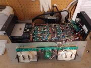
I recommend these level controls for the ultimate WOPL upgrades. I like the Bourns potentiometers, but these sound better, have the tactile "click" and fit into our amplifiers. See second picture:
Full Comp Mule with Goldpoint Potentiometer.jpg

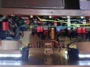
This is the WOPL Full Complementary Mule with the Faceplate bolted on and running with some Classis Rock playing in the background. The dual channel Goldpoint Level Attenuator fits inside the amplifier nicely.
Full Comp Mule Running with Goldpoint Potentiometer Installed.jpg
 

Gepetto

Administrator
Staff member
Joined
May 15, 2011
Messages
14,008
Location
Sterling, MA
Tagline
Old 'Arn Enthusiast
#2
This is a picture of my bench "Mule" Full Complementary PL400 "WOPL" amplifier which I use to test newly assembled WOA Rev G1 Control Boards for customers. Yes, the wiring is long because I need to drop the Faceplate twice per test and sometimes I test two or three boards in one session. Also, note the large Series X 440VAC Line-to-Neutral Safety Capacitors I installed before Joe created his Bridge Rectifier Snubber Board.

In any case, a previous owner drilled a single hole in the otherwise nice Faceplate for a potentiometer. I deleted the Chinese potentiometer when I upgraded the amplifier to Full Complementary operation. The resulting hole bugged me, so I installed a double layer potentiometer because I like to have the input test signal low at Power On with an untested Control Board in place for the first time; my HP 3311A Function Generator is preset to 1.0V RMS and I don't like to turn it down and then recalibrate it every time I test a Control Board.
The 100K dual potentiometer was one I had in my parts drawer and it ended up being unequal from Channel A to Channel B, like the wafers were not "timed" or tracking correctly. This bugged me even more than a blank hole in the Faceplate.
So I searched for "Audiophile Quality" potentiometers (there are many from China). There are inexpensive resistor chain types, which just add more resistors in series to get the input signal down low and each resistor adds some noise. There are Ladder types, which only have two resistors in circuit at once. There are Shunt types, which only use two resistors but change the load impedance as you turn the control.
I finally selected the 24 position Goldpoint Level Control (stepped Ladder Type attenuator) in the 100K value. They can be had in one or more channels (up to 6) and I needed a two channel unit. The price is a bit steep, at $165.00. The P/N is V24-2-100K. Here: https://www.goldpt.com/prices.html
They also have a 47 position Level Control for $246.00, I thought that was a bit much too "Audiophile" for me. These Goldpoint Level Controls use 0.5%, 25ppm, Nichrome Thin Film, surface mount, precision resistors. The switch mechanism components come from Switzerland and the thick, hard gold contacts are "make-before-break" so there are no pops or clicks. Can you tell I really like these Goldpoint Level controls? The sound is actually improved, and the amplifier has more volume at the 12 o'clock position, although this might be a difference in the audio taper from the previous carbon potentiometers. From Goldpoint:
"Starting at full counter-clockwise rotation (OFF), the decibel step sizes are 9, 7, 6, 4, 3 and then 2dB for all 17 remaining steps up to full ON. This Goldpoint defined taper optimizes and is plenty of steps for volume control of most systems. The 15 degree switching, 24-position stepped attenuators provide 62dB of total attenuation."

I recommend these level controls for the ultimate WOPL upgrades. I like the Bourns potentiometers, but these sound better, have the tactile "click" and fit into our amplifiers. See second picture:
View attachment 79048

This is the WOPL Full Complementary Mule with the Faceplate bolted on and running with some Classis Rock playing in the background. The dual channel Goldpoint Level Attenuator fits inside the amplifier nicely.
View attachment 79051
Looks like you are stuck at RevB on the light board Mark, unless you drill a hole higher up :)
 

J!m

Veteran and General Yakker
Joined
Dec 24, 2019
Messages
10,831
Location
Connecticut
Tagline
BOT
#3
I went to a similar attenuator on my headphone amp and the difference was staggering. I’ll never use one of those filthy pots again in my builds.
 

mlucitt

Veteran and General Yakker
Joined
Jun 24, 2011
Messages
3,479
Location
Jacksonville, FL
#4
Looks like you are stuck at RevB on the light board Mark, unless you drill a hole higher up :)
Joe, yes I am using the Rev B Light Board in this old Mule. The PL400 Rev C1 Light Board will not fit on that Faceplate.
I am not using the Sensitivity Selector Switch in this amplifier either. I leave the jumpers at -20db.

"unless you drill a hole higher up"
I cannot even point a drill at a Phase Linear Faceplate - some invisible force pushes the spinning drill bit away. It's eerie.
 
Last edited:

8991XJ

Chief Journeyman
Joined
Oct 8, 2011
Messages
1,226
#5
The Bottlehead Foreplay II I picked up and got the Sony Tektronix 335 scope, too, has a pair of mono goldpoint pots in it. It was a very high quality build for that kit tube preamp.
 

MarkWComer

Veteran and General Yakker
Joined
Nov 1, 2014
Messages
3,505
Location
Gaston, SC
Tagline
Victim of the record bug since age five
#6
This thread leaves me with a question…

A volume control attenuates completely at the most counterclockwise position, and offers no signal resistance when fully clockwise- this we all take for granted. BUT- a “balance” control pot should behave differently, I should think. At the top-dead-center of a balance control, there should be no attenuation to either channel, but the left channel should begin to attenuate at the first clockwise “click” of the balance control- and should continue to increase attenuation the more clockwise the control is rotated. The inverse of this should apply when rotating the control to the left channel.

In other words, fully half of the balance control should offer no resistance depending on which channel is intended to gradually decrease in volume.

Is my supposition incorrect??
 

Gepetto

Administrator
Staff member
Joined
May 15, 2011
Messages
14,008
Location
Sterling, MA
Tagline
Old 'Arn Enthusiast
#7
This thread leaves me with a question…

A volume control attenuates completely at the most counterclockwise position, and offers no signal resistance when fully clockwise- this we all take for granted. BUT- a “balance” control pot should behave differently, I should think. At the top-dead-center of a balance control, there should be no attenuation to either channel, but the left channel should begin to attenuate at the first clockwise “click” of the balance control- and should continue to increase attenuation the more clockwise the control is rotated. The inverse of this should apply when rotating the control to the left channel.

In other words, fully half of the balance control should offer no resistance depending on which channel is intended to gradually decrease in volume.

Is my supposition incorrect??
Your supposition is correct Mark. A balance pot should do in roughly 1/2 turn what a normal pot does in a full turn and the other half turn should be no attenuation at all.

When you are attempting to use a normal 2 gang pot to be a balance pot, compromises need to be made.
 

George S.

Veteran and General Yakker
Joined
Feb 18, 2020
Messages
5,033
#8
That's the way I'm thinking about building mine. With no resistance or attenuation at the center position.
I have the balance pot out of one of my preamps now. Going to tack a jumper across the solder pads and see what it sounds like.
Been using a single Bourne's 10K Linear pot in that unit, with the wiper to ground, and each channel on a outside lug. This is how the very early PL2000 were set up before they went to a dual balance pot.
 

George S.

Veteran and General Yakker
Joined
Feb 18, 2020
Messages
5,033
#9
Sounds excellent with the balance pot removed and the board jumpered.
It's not really any louder.
Maybe use a 23 step 4 pole switch. Make step #12 the center. Use a straight jumper instead of a resistor pair there. Then resistors and more jumpers where appropriate. Each wafer would have half buss wires and the other half resistors on opposing sides of step #12.
Construction would be much simpler than a volume switch and would use half the resistors.
Listened to 3 songs on FM while typing this. Channel separation, definition, and imaging is improved.
 

George S.

Veteran and General Yakker
Joined
Feb 18, 2020
Messages
5,033
#10
I'm finding that my understanding this is flawed. Using buss wire jumpers incorrectly on the switch would upset the impedance if done incorrectly. I'm thinking the impedance needs to remain unchanged while the gain can be changed through resistor or buss wire selection.
Basically the two resistors in circuit need to sum to 50K. One of those two control the selected gain.
If I want full channel gain I can use a buss wire jumper, but it needs wired to a 50K resistor on the ground side.
Looks like I'll need about 12 50k resistors per wafer.
I'll match up the resistors I removed to make 50K pairs in the meantime. Should have good options with those pairs for attenuating the channels.
 

George S.

Veteran and General Yakker
Joined
Feb 18, 2020
Messages
5,033
#12
Mark L, I actually printed a copy of that page yesterday and it's sitting on the bench.
That appears to be the pinnacle for a stepped attenuator balance control.
Thanks.
Attaining that configuration is my goal.
I need to learn more about the preamps input impedance and how it affects the connected devices that drive it.
The stock balance pot is a dual 50K. There may be valid reasons for lowering it to 20 or even 10K.
Trying to get a grip on understanding this, I lack the fundamentals, but slowly getting there.
 

George S.

Veteran and General Yakker
Joined
Feb 18, 2020
Messages
5,033
#13
I'm very tempted to install a red LED in that balance pot hole and use the channel gain settings in the MiniDsp. I do need to always slightly attenuate the left channel due to the furniture in the room.
Naw, I'll get this figured out.
 

George S.

Veteran and General Yakker
Joined
Feb 18, 2020
Messages
5,033
#15
Joe, I have a Acurus L10 sitting under the bench, and it's a nice one.
It just doesn't do it for me when I look at it. No mojo.
 

George S.

Veteran and General Yakker
Joined
Feb 18, 2020
Messages
5,033
#19
Oh yes Mark L., the Acurus blows the PL2000 out of the water in measurements.
However, those differences aren't audible to me. Noise, distortion, crosstalk figures are higher on the PL, but below my threshold of sensing any difference. Upgraded, it's a nice and very usable "antique" preamp.
So I favor the PL for matching the rest of the system, the mojo.
And, it has a nice phono section built in that meets my requirements. I tested mine after upgrading, with a reverse RIAA filter board, with excellent results.
The Motronix board and instructions I used.
 

Attachments

Top