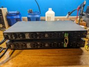
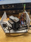
Furman power sequencer.

George S.

Veteran and General Yakker
Joined
Feb 18, 2020
Messages
5,022
#21
Both are up and running after recaps and replacing two dip 14 IC's on one board.
I've been frequenting HP test equipment forums, blogs, videos, etc, and those guys seem to always install a socket when they replace a IC, so I also did so.
I'll let these burn in overnight. Tomorrow I'll check that the relay contactors are good and see about wiring the remote functions on the units together.
I'd like to get the two units to sequence with one push button press on either unit, but the manual is rather lacking info as usual.
Time to walk the dog
 

Attachments

George S.

Veteran and General Yakker
Joined
Feb 18, 2020
Messages
5,022
#22
Success. Both units sequence with one button press on either unit. Requires the correct jumper setting on the logic/relay board and one to one wiring on the remote port. Silver plated Teflon insulated wire of course :).
Now to learn how to look at the 120 VAC output and verify it's correct and noise free, without blowing up my test equipment!
 

Attachments

George S.

Veteran and General Yakker
Joined
Feb 18, 2020
Messages
5,022
#23
So, there appears to be only two safe ways to look at 120 VAC on a scope.
The first is to use a high $ isolated differential probe which I don't have.
The second is to use a transformer.
Supposedly any noise that's visible at 120 VAC will also be visible on the transformers outputs.
And, I have this old Regency 13.8 VDC output power supply that I really have no use for.
So, I'll mod this, and see.
 

Attachments

grapplesaw

Veteran and General Yakker
Joined
Aug 13, 2014
Messages
2,775
Location
Vancouver
Tagline
---
#24
Both are up and running after recaps and replacing two dip 14 IC's on one board.
I've been frequenting HP test equipment forums, blogs, videos, etc, and those guys seem to always install a socket when they replace a IC, so I also did so.
I'll let these burn in overnight. Tomorrow I'll check that the relay contactors are good and see about wiring the remote functions on the units together.
I'd like to get the two units to sequence with one push button press on either unit, but the manual is rather lacking info as usual.
Time to walk the dog
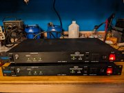
George were the ic’s what was causing it not to work? Of did you just refresh them as it was apart?
 

George S.

Veteran and General Yakker
Joined
Feb 18, 2020
Messages
5,022
#25
Glenn, I suspect it was one of the two dip 14 IC's I replaced, a TL084CN JFET opamp, or a HEF4013 flip flop. I did have one Jamicon 22 uF 35 V electrolytic that tested borderline on the DER EE LCR Meter.
 

George S.

Veteran and General Yakker
Joined
Feb 18, 2020
Messages
5,022
#26
Pulled the DC regulator board and I'm left with a center tap transformer producing appx 19 VAC on each leg. Running it on the isolation transformer with the scope plugged into normal mains.
It's a good opportunity to learn more about the DSO.
Been looking at FFTs of the 60 Hz wave. Running the probe at X10 for safety sake.
Going to play with this awhile and store the most interesting FFTs, then compare them to what the Furmans are outputting.
I need the verify a clean output before I use them in the system.
I should probably figure out some way to load test the Furmans . Maybe load them with a resistive element like a electric heater. Dual sockets so it would be easy to monitor each of the four 120 VAC legs in turn with the present setup.
Going to have 2 400 WOPLs plugged into one Furman, and a 700 WOPL and PL300S2 plugged into the other.
The amps should run cool and just idle along, hardly working in a four way active system.
Time to walk the dog.
I'll put the cover and feet back on the power supply and mark it 19 VAC Output with a Sharpie.
 

Attachments

wattsabundant

Chief Journeyman
Joined
Apr 26, 2011
Messages
932
Location
Central Ohio
#27
I wouldn't tear apart a good power supply. Most people have a wall wart power supply lying around that is a 6-12 volt output.

You can look at line voltage without a transformer. Assuming your scope has a 3 wire power cord you lift the ground wire on the power cord. Not the safest thing to do. Any time I've done this I soldered a 10 ohm 1/4 watt resistor in series with the ground lead of the probe. A 1/10 amp pico fuse would work to. That could also make the scope chassis hot.

The transformer method will work ok for 60 Hz but if you want to test for high frequency noise on the line you'll need an instrument grade transformer.

With a dual trace scope you can use two probes and set the mode to add or differential. This assumes the scope inputs are both grounded. The probe ground wire is not used. Depending on the scope one channel may need to be inverted.

I bought some isolation probes and a USB scope on Amazon earlier this year to show real time power line waveforms on a class room projector. I thought the probes were only a $100 or so but can't find any at that price now on Amazon.
 
Last edited:

George S.

Veteran and General Yakker
Joined
Feb 18, 2020
Messages
5,022
#29
Well, I tested these by plugging in a window air conditioning unit and a small space heater. Was probably close to tripping the units internal 15 amp breaker.
I can see no change in waveforms or FFT's between the wall socket and the units output.
Calling these done and ready to use.
Going to watch for some isolated differential probes that will allow future indepth testing.
 
Top