mlucitt
Veteran and General Yakker
<sarcasm>ATTRACT lightening??? Thats silly

<sarcasm>ATTRACT lightening??? Thats silly
I shoulda slid a gotcha in there.Guess I still need an interpreter. you shoulda slid a HUH? in there
Hi guys,
Well I decided to update the line cord to a three prong type. The ground wire went under one of the nuts securing the xformer and the hot and neutral wire extended to a double pole single throw switch which I mounted to panel. I know I hesitated but put switch on panel.
The l.e.d lites shows when power is on.
I'm still waiting for light kit to complete the amp. Got backplane assembly done and can't wait to hook up control board.
Been busy with honey do and getting house ready for winter.
I'll keep everyone posted.
Wayne in Dwight
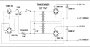
Joe, I was looking at the old PL 400 and 700B schematics and it shows the secondary windings of the power transformers are center-tapped to balance the rail voltages. Is this 0V connection "grounded" inside the transformer housing? Because I don't see this connection inside the amp.You may end up with hum problems Wayne by connecting the safety ground to chassis. It is system dependent.
Joe, I was looking at the old PL 400 and 700B schematics and it shows the secondary windings of the power transformers are center-tapped to balance the rail voltages. Is this 0V connection "grounded" inside the transformer housing? Because I don't see this connection inside the amp.
The reason I ask is that an old guitar amp technician's trick is to attach the power wire ground (green wire) to the same point as the transformer center tap 0V point to reduce ground loops and hum. The theory is that the out-of-phase secondaries cancel each other and these two connections to the chassis at the same point prevent a ground loop because there is no longer a path through the chassis. Does this make sense to you?
Interestingly, Nelson Pass used a rectifier bridge on his amps for a ground isolation. The attached view shows dual output secondaries, but could be just the same with a single center-tapped output secondary.
Obscure and obvious all at the same time. Thanks.Hi Mark
Those center taps are typically the 2 magnet wire with woven sleeving brought out and soldered to the middle of the copper bus bars. It is a typical full wave center tapped transformer configuration.