Early PL400 Time to Upgrade

oldphaser

Chief Journeyman
Joined
Sep 8, 2012
Messages
848
#21
If you go full comp you'll want the backplane boards also. Better soundstage, tighter bass...just better all around..
So this has more to do with converting the amplifier to a fully complementary output than something to do with using a WOPL backplane board.
This can also be accomplished by re-wiring the output stage like Phase Linear did on all of their fully comp 400 and 700 series two amplifiers.
 

Greg_M

New Around These Parts
Joined
Feb 22, 2020
Messages
14
Location
Lakewood, Wa
#23
Well not much to go on, but I guess that I will be re-wiring the output stage like Phase Linear did on their fully comp 400. Budget is tight and I have a lot of time on my hands. :)
 

wattsabundant

Chief Journeyman
Joined
Apr 26, 2011
Messages
932
Location
Central Ohio
#24
Before the White Oak driver board and backplanes were available, I converted a few 700B's and 400's to full comp. Unless a person really understands the circuitry I wouldn't recommend going that route. Besides rewiring the negative output stage, Q7 gets installed backwards and a few other changes get made.
 

Greg_M

New Around These Parts
Joined
Feb 22, 2020
Messages
14
Location
Lakewood, Wa
#25
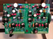
White Oak Rev G1 Board complete, Easy build took about 5 hours, didn't want to rush. Built as Full Comp. decided to bite the bullet and get the backplane board, looked at the schematic, hand wiring was doable, but then I am not a glutten for punishment. As they say it didn't happen if there is not a picture, so one attached. PL14-20 Rev G1.jpg
 

laatsch55

Administrator,
Staff member
Joined
Jan 14, 2011
Messages
74,829
Location
Gillette, Wyo.
Tagline
Halfbiass...Electron Herder and Backass Woof
#26
White Oak Rev G1 Board complete, Easy build took about 5 hours, didn't want to rush. Built as Full Comp. decided to bite the bullet and get the backplane board, looked at the schematic, hand wiring was doable, but then I am not a glutten for punishment. As they say it didn't happen if there is not a picture, so one attached. View attachment 40322

Lookin good...
 

Greg_M

New Around These Parts
Joined
Feb 22, 2020
Messages
14
Location
Lakewood, Wa
#28
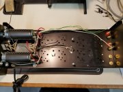
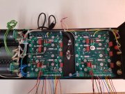
Almost done. Ran into some minor problems to be expected with such an early unit. Had to reposition the capacitors to have clearance for the meter, also had to shorten the driver board standoffs as the meter hit the transistor cooling fins
. Backplane.jpg wopl400.jpg
 
Joined
Feb 18, 2018
Messages
186
Location
Southern Indiana
Tagline
---6 and 7 days work week, no end in sight
#31
Almost done. Ran into some minor problems to be expected with such an early unit. Had to reposition the capacitors to have clearance for the meter, also had to shorten the driver board standoffs as the meter hit the transistor cooling fins
. View attachment 41158 View attachment 41159
just curious, what type of wire you used on the RCA inputs to control board?
 
Joined
Feb 18, 2018
Messages
186
Location
Southern Indiana
Tagline
---6 and 7 days work week, no end in sight
#34
ok, that would be better than the twisted unshielded wire that is in my PL400. I'm thinking of replacing the wire with RG 316 coax..
 

wattsabundant

Chief Journeyman
Joined
Apr 26, 2011
Messages
932
Location
Central Ohio
#35
I'm not convinced that it's necessary to replace the twisted pair. Twisted pair cancels out noise and on the 400 it's a short run. In support of this notion, consider category 5 network cabling. It consists of 4 twisted pairs and can be run over relatively long distances in buildings and often in the vicinity of power cables. If you use 1 wire from one pair and one wire from another pair, the lights on the network cards come on and it appears to be connected. However the, the network will crash. How do I know? I used the wrong wiring standard when I wired my house 20 years ago. A friend quickly diagnosed the problem. I made the proper connections and it still runs great today.

If you must change the cable, use Belden 8451. That's what is used on the 700 level controls. Use proper terminating practices for the drain wire.
 

db916gt

New Around These Parts
Joined
May 19, 2019
Messages
3
#37
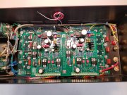
Thanks for the information, my meters look like the Midland in the second picture. My control board is a slightly earlier version of the first board you show. Where my board has traces cut by hand, your board has the traces modified before production.
View attachment 39995 View attachment 39996
Does anyone have documentation on how the adjustments work on this specific 3 trimmer pot per channel PL400 Control pwb please? I assume (SWAG), they work the B+ / B- bias, and the third is idle current? Where are the measurements taken from, etc... Thanks for any help.
 

db916gt

New Around These Parts
Joined
May 19, 2019
Messages
3
#39
Are you talking about the PL400C control board in a stock 400??
yes, but for an early 400, as is pictured in this forum, it has the 6 trimmer pots on the control board.. I know the two trimmer pots on the PL36 board, and the PL14 series boards.. but I got an old one like pictured in this session.. looking for some direction / documentation on how to set up the amp.. Thanks.
 

mlucitt

Veteran and General Yakker
Joined
Jun 24, 2011
Messages
3,469
Location
Jacksonville, FL
#40
The PL400C board is a bit different. Let's take the Left Channel (left side of the board) first. The potentiometer at the top is R14, it is the Bias Adjustment. With the amp off connect a pair or alligator clip equipped wires across R24 (the 10 Ohm 1/2W resistor in each output bank) and then to your digital voltmeter. Turn on the amp and let it warm up for 15 minutes. With no inputs or outputs connected, read the voltage and adjust R14 to get 350mV on the meter.
You will then conduct the same test but connect the alligator clips across R41 (10 Ohm 1/2W) and verify the voltage reading is within 20% (350mV +/-70mV), so minimum 280mV and maximum 420mV.

The potentiometer on the left side of the board is R8, it is the DC Offset Adjustment. With the digital voltmeter connected to the left speaker outputs, adjust R8 for 0V or as close as you can get with the amp at operating temperature.

Repeat these tests for the Right Channel. The corresponding adjustment pots are just moved over to the right side of the board.

I hope this helps.
 
Last edited:
Top