Early PL400 Time to Upgrade

Greg_M

New Around These Parts
Joined
Feb 22, 2020
Messages
14
Location
Lakewood, Wa
#1
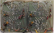
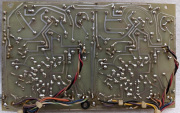
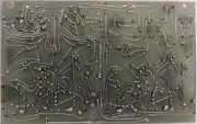
I guess it's time, I purchased my PL400 new in 1972, build date 42nd week of 72, S/N 17, Edmonds, WA. It's been a faithful amp with only one problem about a year after I got it. Something failed and it trashed a set of Bose 901 speakers. I have to give it to PL as they repaired no charge as did Bose. So it's WOPL time, hope to get another 20 years out of it. Unfortunately my PL400 uses the Argonne meters not the later Jewell ones so I can't use the WO Light Board Kit. Here is a picture of my control board, it doesn't match any schematic I have found, must have been an early short run board. pl400.jpg
 
Last edited:

Greg_M

New Around These Parts
Joined
Feb 22, 2020
Messages
14
Location
Lakewood, Wa
#3
The meters are not marked in any way, just going by the information in my service manual. The meters are lit by fuse style bulbs and the meter circuitry uses a full wave bridge rectifier which I have not been able to find in any of the schematics I have. The service manual I have says that it is for Serial numbers 000-000 thru 743-300, but the schematics do not correctly show my control board.
 

mlucitt

Veteran and General Yakker
Joined
Jun 24, 2011
Messages
3,469
Location
Jacksonville, FL
#4
My PL400 Service Manual says "Prepared 6/76, 1st Revision 6/80, 2nd Revision 6/81. Is your Service Manual hardcopy or digital? If digital, could you post a copy here?
Your Service Manual schematic will be replaced by the WOPL schematic, a much better design and execution of the original PL concept using state of the art components, thus enhancing the reliability and performance of your PL400.
 

Greg_M

New Around These Parts
Joined
Feb 22, 2020
Messages
14
Location
Lakewood, Wa
#5
My Service Manual is undated but I would guess that it dates from around 1972 or early 1973 as the schematic does not correspond to my schematic dated Aug 9, 1973. The copy I have is a hard copy, but I can make a scan. There are also hand drawn circuit changes to the schematic that add indicators for clipping, overtempt and gain controls.

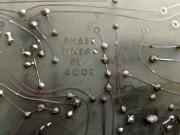
The circuit board in my PL400 has no ID on it, it looks to be a short run board, possibly a prototype as there are several trace cuts and component addons. There is no solder mask or Component ID.
 

Gepetto

Administrator
Staff member
Joined
May 15, 2011
Messages
13,944
Location
Sterling, MA
Tagline
Old 'Arn Enthusiast
#6
My Service Manual is undated but I would guess that it dates from around 1972 or early 1973 as the schematic does not correspond to my schematic dated Aug 9, 1973. The copy I have is a hard copy, but I can make a scan. There are also hand drawn circuit changes to the schematic that add indicators for clipping, overtempt and gain controls.

The circuit board in my PL400 has no ID on it, it looks to be a short run board, possibly a prototype as there are several trace cuts and component addons. There is no solder mask or Component ID.
Hi Greg
Did Bob Carver engrave his initials in that board? What circular builder name is assigned to that amp?
 

oldphaser

Chief Journeyman
Joined
Sep 8, 2012
Messages
848
#8
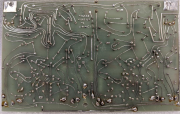
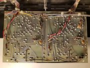
Phase Linear used a variety of revisions of the PL400C pc boards before they started using the PL14 series of pc boards in 400 series 1 amps. I have (5) examples of the versions of the PL400C. In the attached photos below are (2) early versions with no notation on the backside of the pc board and then PL400C, PL400C1 and PL400C2. The earliest versions are not noted in any Phase Linear 400 service manual. Perhaps the best information available on adjusting the DC offset trim-pots (on the earlier pc boards) can be found in a 700 series 1 service manual.

The VU meters used in 400 series 1 started with the Midland meters which were the most unreliable meters Phase Linear ever used.
They also used Jewell and Honeywell (which were essentially the same company) and Dixson.

If my memory serves me correct, the Midland VU meters are a bit smaller than the Jewell, Honeywell and Dixson meters Phase Linear used and also used a smaller meter bezel.

Argonne VU meters were sold by Lafayette Electronics from 1960-1975. However I never saw one that was large enough to fit into a 400 series 1 amp meter bezel. To my knowledge Phase Linear only used Argonne VU meters in 700 series 1 amplifiers.
 

Attachments

Greg_M

New Around These Parts
Joined
Feb 22, 2020
Messages
14
Location
Lakewood, Wa
#9
Thanks for the information, my meters look like the Midland in the second picture. My control board is a slightly earlier version of the first board you show. Where my board has traces cut by hand, your board has the traces modified before production.
pl400b.jpg pl400c.jpg
 

oldphaser

Chief Journeyman
Joined
Sep 8, 2012
Messages
848
#10
When the Phase Linear 400 series 1 amp was first being developed by Bob Carver in late 1971 it was handed off to Terry Phillips to put into production. It has been many years since I last talked to Terry. Terry also worked for Boeing like I did and he bounced back and forth between the Seattle area and Wichita. Terry's nickname at Phase Linear was Mr. Amplifier.
 

62vauxhall

Veteran and General Yakker
Joined
May 14, 2014
Messages
2,321
Location
Southwest Kootenays BC
Tagline
No such things as bad days, just bad moments
#12
When the Phase Linear 400 series 1 amp was first being developed by Bob Carver in late 1971 it was handed off to Terry Phillips to put into production. It has been many years since I last talked to Terry. Terry also worked for Boeing like I did and he bounced back and forth between the Seattle area and Wichita. Terry's nickname at Phase Linear was Mr. Amplifier.
If the 400 went into production in '71 how long was it produced as a 4 fin? When did they become 8 fin?
 

oldphaser

Chief Journeyman
Joined
Sep 8, 2012
Messages
848
#13
If the 400 went into production in '71 how long was it produced as a 4 fin? When did they become 8 fin?
The Phase Linear 400 series 1 amplifier went into production in December 1971.

The change-over from the 4 fin to 8 fin heat-sinks occurred sometime around November 1974.

It was as a result of the 1/3rd power pre-conditioning for 1 hour as was required by the Federal Trade Commission "Power Output Claims for Amplifiers Utilized in Home Entertainment Products" (a.k.a. Amplifier Rule) 16 CFR Part 432 which was written May 3, 1974 and took effect six months later on November 4, 1974.

NOTE: This requirement was later relaxed and an article "FTC Eases Audio Amp Power Rule" appeared in Billboard magazine Oct 11, 1975.
"...."However it is our opinion that use of the automatic recycling method permitting a piece of equipment to recycle (thermally cut off or on) automatically until 'on time' of one hour is accumulated is not inconsistent with the language of 3(c) and therefore constitute compliance with the Rule"

The verbiage on the front panels on the 400 and 700 were also changed in November 1974 as a result of the FTC's activities. (see paragraphs 6 and 7 in Billboard Oct 26,1974 article "Audio Firms Must Backup RMS"). As an example, the 400 series 1 sated "Four Hundred Watts R.M.S." and was changed to "Laboratory Standard Amplifier". Apparently Crown did not like this because their DC-300 stated "Laboratory Power Amplifier".

Further effects of the FTC spec upon the manufacturer's:
As was also stated in the Billboard magazine article:"...many firms have had to de-rate stated power output capability or incorporate costly design changes."
Crown also added some clip-on heats-sinks for a while in an effort to meet the FTC spec. I have posted some pictures of this on another posting. Dynaco also modified their sales brochures and took out an ad in The Audio Amateur magazine 4/1974 . (see pdf below)

There is lots more to the story of the FTC "amplifier rule" which was relayed to me by A.P. Van Meter (former McIntosh, University Loudspeaker and Phase Linear chief design engineer). I may have already discussed this in one of my prior postings.

I also have dozens of articles relating to the debate than occurred during the early to mid 1970's concerning the FTC "amplifier rule".


It should also be noted that the FTC spec has been revised several times since 1974 and the pre-conditioning requirements have been further relaxed. If my memory serves me correct, the most recent comments were released on January 26, 2010:
https://www.ftc.gov/sites/default/f...tainment-products/100126homeentertainment.pdf

Earlier documents may also further add to one's understanding:
December 22, 2000:
https://www.ftc.gov/sites/default/f...roducts/001222traderegulationrulerelating.pdf

July 9, 1998:
https://www.ftc.gov/sites/default/f...regulationrulerelatingtopoweroutputclaims.pdf


Ed
 

Attachments

Last edited:

62vauxhall

Veteran and General Yakker
Joined
May 14, 2014
Messages
2,321
Location
Southwest Kootenays BC
Tagline
No such things as bad days, just bad moments
#15
I have revised/edited my previous post (#13) several times.
Thanks for the info and explanation. I was anticipating the reason was more or less to address a shortcoming of the amplifier from a performance standpoint.

So by the sounds of things, a 400 could have happily continued as a 4 fin if legislated amplifier power measuring methods were not established.
 

oldphaser

Chief Journeyman
Joined
Sep 8, 2012
Messages
848
#16
Thanks for the info and explanation. I was anticipating the reason was more or less to address a shortcoming of the amplifier from a performance standpoint.

So by the sounds of things, a 400 could have happily continued as a 4 fin if legislated amplifier power measuring methods were not established.
Yes the amplifier would more than likely continued as it was if it were not for the FTC.

A.P. Van Meter told me about the phone calls he was receiving from the FTC on a regular basis about what Phase Linear was going to do to meet the spec. There was little they could do to the 700B as there was no more room to add additional heat-sinking without a major(?) revision/change. There was something they could do with the 400 and that is by adding additional heat-sinking.

Phase Linear could have also added fans like BGW did. Brian G. Wachner (BGW) was a big proponent of the FTC 1/3rd power spec and there a AES paper written by him on the subject, and a Audio magazine article dated Feb 1975 pgs 22-26, 28 and follow up letter to the editor in April 1975.

Phase Linear was also working on a dual rail secondary like the one they used on the DRS series of amplifiers that would have when completed met the spec. However, the DRS series would be several years off and it was released in part to the release of the IHF-A-202 and the dynamic headroom spec that they sought to capitalize on. This was also in an era where CD's were also about to be released.

The DRS-900 was rated at 150 watts RMS per channel. It had "900 watts of peak power". When I measured them they would do approximately 420 watts per channel into a 8 ohm load. (NOTE: I can't remember at the time what the THD spec I used was; i.e. .015% as was rated at 150W, .02% as was rated at approximately 450 watts or 1% (which is a figure used to represent something near clipping) or if it was single channel driven or both channels driven. It was measured from 20Hz to 20KHz). What Phase Linear was marketing at that time for the DRS-900 was the Dynamic Headroom at 4.77dB. DRS stood for "Dynamic Range System". List Price was around $1,100. Very few were sold. Perhaps, Phase Linear would have been better off marketing it as a 400 watt per channel amp?

I also asked A.P. if he remember the name of the individual(s) he talked to at the FTC. He could not recall if it was any of the names I mentioned; Carthon Aldhizer, William Dixon, Richard Givens, Elliot Finberg or Charles Tobin.

Ed
 
Last edited:

oldphaser

Chief Journeyman
Joined
Sep 8, 2012
Messages
848
#18
I got to thinking about this some more.

A.P had mentioned that they were working on a dual rail secondary.

Phase Linear started working on the Dual 500 (in 1977) long before the DRS series (in 1981/2) and it too had a dual rail secondary. However it starts on high rail and only switches to low rail when the amp is driving a more difficult load like 20KHz at rated output into a 4 ohm load. There is a Hi-Z and Lo-Z circuit utilizing a relay on the Dual 500.

The DRS-900 starts on low rail and switches to high rail at almost exactly 150 watts. It uses some Darlington transistors in the process.

Clyde S. Yamamoto who built the higher power amplifiers like the 700's and Dual/D-500's also built several custom Dual/D-500's. They have a black front panel like a PRO700 series two and it has CSY1.5 silk-screened on it. I saw one or two of them at Dean's house many years ago. If my memory serves me correct, Clyde set it up to run low rail and then high rail like the DRS style circuitry used. One of the two was not very reliable and was converted back to a stock Dual/D-500 by Dean. Since the CSY1.5's had the black pro series front panel, more than likely it was made around the same time as the pro series products were introduced in 1981 and the DRS's were under development.

Ed
 

Greg_M

New Around These Parts
Joined
Feb 22, 2020
Messages
14
Location
Lakewood, Wa
#19
OK, I pulled the trigger on a White Oak PL14_20 RevG1 Dual Mono Control Board. My Question to the hive mind here is, what are the pro's and con's
for Quasi or Full Comp?
 

laatsch55

Administrator,
Staff member
Joined
Jan 14, 2011
Messages
74,829
Location
Gillette, Wyo.
Tagline
Halfbiass...Electron Herder and Backass Woof
#20
If you go full comp you'll want the backplane boards also. Better soundstage, tighter bass...just better all around..
 
Top