DBT not dimming

Chafoweeth

New Around These Parts
Joined
Jun 25, 2018
Messages
11
Location
Kenmore, WA
Tagline
---
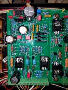
I am installing a new control board into my PL400. I misinterpreted the wiring diagram on the 1st run and my DBT light dimmed a little after the caps charged, but stayed bright. I *think* my miswiring was pretty benign; there certainly was no smoke, but the unfused b+ and the ground were hooked up to terminal points with no connections on the circuit board.

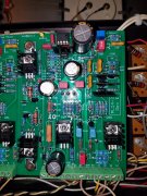
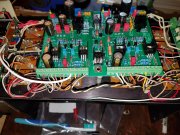
I am confident that I have things hooked up correctly now, but I am still getting the light to dim only a bit, and the front lights do not turn on. However, if I remove the fuse from either channel, things seem to settle into what I would expect. That is, the light dims appropriately, and the face-plate lights up.

I have already installed new filter capacitors, the new light board, and the protection circuit.

Any ideas what I might have nuked, and/or where I should look for errors?
Thanks!
 
Eric is your bias adjusted all the way down on both channels?
 
With the bias set at minimum, what bias voltage are you reading? Have you measured the output offset and is it within a millivolt of zero?

Can you post some pictures for the experts on this forum to see?
 
The DBT is 100W
The bias voltage and the DC offset for the channels are about the same.

The bias was measured between the bias test point and the ground test point. The DC offset was measured across the terminals of the protection board before the relay.

For the Left it is ~1.8V
For the Right it is ~.7V
 

Attachments

  • 20200221_205822.jpg
    20200221_205822.jpg
    2.2 MB · Views: 20
  • 20200221_205924.jpg
    20200221_205924.jpg
    2.2 MB · Views: 21
Hi Eric
Are those voltages your output offset readings? Are those milliVolts? Your post says volts. What is your B+ and B- measuring?
 
Hi Eric
What jumps out at me is that the right channel appears to have the MJE15034 and MJE15035 in the wrong positions, swapped. The left channel appears correct. This will cause the problem you are observing.
 
A better view of the wiring connection section of the board will be helpful too.
 
Thanks for the help! I will work on getting those swapped. Here is the wiring that I had:
 

Attachments

  • 20200222_110156.jpg
    20200222_110156.jpg
    4.5 MB · Views: 12
That must have been all there was. Everything is looking great now.

.1 mV DC offset on both channels and the un-adjusted bias is ~ .193V for the left and ~ .183 V for the right.

Thanks again for your help and patience!
 
Just a note for future reference:
If any of your output transistors are fused, the DBT won't dim.
I had a severe failure of some transistors in my left channel and turned the switch on my DBT to "normal" instead of "test" by accident, burned a number of things on my control circuit and some emitter resistors.
 
And them 40 year old outputs??? I've seen them go 3 at a time.............. tick tick tick tick....................
 
At least then those trannies are out of the food chain. Kinda like Darwin's survival of the fittest. Natural selection of outputs, where MJ21196G NPNs are King of the Jungle.
 
I found a new use for my transistors out of the amps I strip..... I hide behind the truck and throw them at the illegals coming north... Si......
 
Back
Top