
- Joined
- Jun 20, 2013
- Messages
- 696
- Location
- Kapiti Coast, New Zealand
- Tagline
- Path under Coastlands overbridge
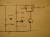
Common sense time delay relay circuit
I have a simple circuit for a time delay relay that really is child's play / Kinderspiel. It's just a voltage regulator error amplifier modified by adding a capacitor to the usual zener diode / resistor network on the base of a transistor and a relay coil with a commutating diode on the collector.
The 1N4001 discharge diode and is not essential for operation of the circuit but may be desirable in applications requiring a fast reset. The discharge resistor is not required if another circuit running off the same power supply draws sufficient current at low voltage. Suggested value for charge resistor 10K ohm at 12 volts. Suggested transistor BC337. Suggested value for discharge resistor 3.0K ohm. The time delay can be adjusted by changing the value of the charge resistor, capacitor or voltage of the zener diode. The zener diode can be a higher voltage, but can't be any lower than 5.1 volts because very low voltage zener diodes tend to have unpredictable characteristics a low current levels. For 5 volt operation of timer circuit use a LED in place of zener diode and change capacitor value to at least 1000uF for a similar time delay.
This circuit is useful in de thump for amplifiers and inrush limiters for switch mode and other types of power supplies. Some types of transformers, especially toroidal draw a very large surge of current from the AC mains until the core is magnetized. This circuit can be used in combination with a surge rated power resistor protected by a thermal cut out in these inrush limiting applications. The relay can be connected in parallel with a triac set up with another timer and trigger circuit with zero voltage crossing detection such as an opto triac driver with a zero voltage crossing detection circuit built in, to prolong the life of relay contacts.
Last edited:


 I missed that on my first read.