Build a stepped balance attenuator.

George S.

Veteran and General Yakker
Joined
Feb 18, 2020
Messages
4,932
#1
I'm building another for the test unit, so I'd thought I'd start a "how to" thread for those interested.
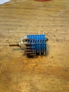
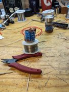
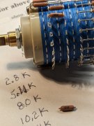
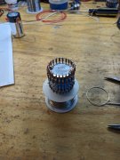
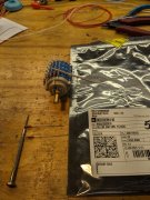
The left channel circuitry is closer to the front, so here I'm loading the left channels 50k resistors which provide 50k impedance and no signal attenuation.
It gets a little confusing, but it'll make sense as we progress.
The important thing to note is to prep each resistor precisely, keep the printed value facing out, and soldering.
The switch plastic readily melts. So keep the resistor at the top of the tab slot, use fine diameter solder and a good clean and tinned tip. Get in, heat the tabs top and lead, apply solder, and get out. Don't melt the plastic or attempt to fill the slot.
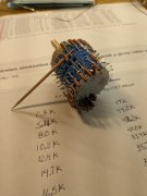
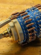
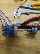
Later, we'll be inserting another resistor into the bottom of the certain tab slots and we need them open.
Easy to do as we'll see.
 

Attachments

George S.

Veteran and General Yakker
Joined
Feb 18, 2020
Messages
4,932
#3
All the 50ks' are installed from 12-6 o'clock for each channel.
This is a 24 step switch, so it'll have a position just to the right and left of 12 o'clock with no signal attenuation at all.
Made a black sharpie line at 12 o'clock. The taps are at the bottom at 6 o'clock.
Time to break.
Next time we'll add the paired attenuating resistors that sum to 50k, the ground rings, and the leads to the taps.
 

Attachments

Last edited:

George S.

Veteran and General Yakker
Joined
Feb 18, 2020
Messages
4,932
#5
Back at it.
I used Neville Roberts' calculator for generating the attenuating pair values.
In this case I wanted linear with 0.5 dB between each of the twelve steps on both sides of the black sharpie 12 o'clock mark.
Results are very precise. Unfortunately that precise value resistor may not be available, or it's very expensive.
So order the closest values that make sense, and yield close to 50k as the sum for the resistor pair.
Yes, this is designed to be a 50k pot, and the values just need to be close, not exact
Later we'll actually measure the completed attenuator, and this will be clearer.
Oh, and Digikey has a much better selection of these expensive low noise 1/8W Dale RN55 "military " resistors.
And of course, theirs plenty of choices of other resistors.
 

Attachments

George S.

Veteran and General Yakker
Joined
Feb 18, 2020
Messages
4,932
#6
The first attenuating resistors are in place for each channel. These are 2.8k and at this point get soldered only on the inward side, as we'll add a 47k to the outward side later.
Note the black sharpie mark at 12 o'clock, the non attenuating wire, then the first attenuating resistor.
2.8k plus 47k equals 49.8k. Close enough.
Once again we're placing the resistor at the top of the solder tab slot and applying heat and solder only at the top. Don't melt the plastic!
 

Attachments

George S.

Veteran and General Yakker
Joined
Feb 18, 2020
Messages
4,932
#7
It's easy to open and reassemble the switches, but there's no need to.
To place these attenuating resistors, carefully grasp the very top of the solder tab and bend it over some, making sure it bends at the tabs window, not at the base.
Then pop the resistor in place with thumb and a little flexing of the bent tab with small precision needle nose. Nothing to it after you've done a few.
Then straighten the tab, elevate the resistor to maximum with toothpick, rotate so value is visible, solder only the inward side.
 

Attachments

George S.

Veteran and General Yakker
Joined
Feb 18, 2020
Messages
4,932
#10
Back at it.
The next resistors are the most difficult.
Requires a "third hand" and longer time with the iron on the tab.
In the photo the 5.11k attenuating resistor is mounted on the switch. The resistor in the third hand is the complementary 44.2k.
5.1k plus 44.2k equals 49.3 k.
Close enough to 50k.
 

Attachments

Gepetto

Administrator
Staff member
Joined
May 15, 2011
Messages
13,807
Location
Sterling, MA
Tagline
Old 'Arn Enthusiast
#11
Looks like George had trouble sleeping last night, thinking about his stepped attenuator...
 

George S.

Veteran and General Yakker
Joined
Feb 18, 2020
Messages
4,932
#12
It's a retirement issue Joe.
Worked extremely long hours for 31 years of trucking and slept well.
Now, 4-6 hrs is it for 1st sleep.
Then 1-2 hrs for 2nd sleep.
Long ago I researched sleep because I was practicing lucid dreaming, and learned about the pre industrial revolution sleep patterns of our ancestors.
I've reverted to a natural sleep pattern with retirement, and I'M LOVING IT!
 
Last edited:

mlucitt

Veteran and General Yakker
Joined
Jun 24, 2011
Messages
3,446
Location
Jacksonville, FL
#18
George, trying to decide how the cost of an assembled attenuator compares to a DIY assembly.
How many hours do you think the assembly took from start to finish?
 

George S.

Veteran and General Yakker
Joined
Feb 18, 2020
Messages
4,932
#19
Mark L., probably about four to five hours once I had the parts.
And it's a slow leisurely assembly that requires concentration and focus because the resistors must be cut and assembled precisely.
It'll test your soldering skills for sure.
I wouldn't want to build a bunch of them, but one or two are a interesting puzzle project to assemble.
A volume control would be much easier to do first, but it's hard to beat the prices on the AliExpress ones, once you price the resistors on Digikey.
Less expensive resistors are a real option.
 

mlucitt

Veteran and General Yakker
Joined
Jun 24, 2011
Messages
3,446
Location
Jacksonville, FL
#20
4-5 hours is not bad. but at $50 per hour, that would be $200-$250 and likely less expensive to buy one assembled in the long run.
I would not trust AliExpress or any other Chinese Attenuator. But a US stereo 47 position level control, assembled, runs $246. The blank level control is $123 with no surface mount resistors included.
https://goldpt.com/prices.html
 
Top