You are using an out of date browser. It may not display this or other websites correctly.
You should upgrade or use an alternative browser.
You should upgrade or use an alternative browser.
Birth of a New Model One
- Thread starter Vintage 700b
- Start date
That connection of chassis and DC ground is via a coupling capacitor only and carries microamps of current. You can either use the nylon washer or not, - your choice with no difference in results.
Is there a reason you do not recommend populating R23 to help discharge the coupling cap?That connection of chassis and DC ground is via a coupling capacitor only and carries microamps of current. You can either use the nylon washer or not, - your choice with no difference in results.
Adding a resistor creates a DC pathway which invariably leads to ground looping in equipment that has multiple safety grounded pieces of equipment such as the preamp. For example, my Acurus has a DC pathway from its DC ground to the chassis safety ground. Adding a resistor in that location in the Model ONE would open the system up to having multiple DC ground connections to safety ground and lead to the ground loop condition. It would be OK if the Model ONE was the only equipment that made that DC to Safety ground connection, but that is very unlikely to exist in most systems.Is there a reason you do not recommend populating R23 to help discharge the coupling cap?
BTW, the voltage between DC ground and chassis ground in my current system setup is 0.000V so there is no discharging necessary for that capacitor.
Thanks for the clarification, I did not consider the amp in a system with other components with respect to potential ground loops involving DC ground.Adding a resistor creates a DC pathway which invariably leads to ground looping in equipment that has multiple safety grounded pieces of equipment such as the preamp. For example, my Acurus has a DC pathway from its DC ground to the chassis safety ground. Adding a resistor in that location in the Model ONE would open the system up to having multiple DC ground connections to safety ground and lead to the ground loop condition. It would be OK if the Model ONE was the only equipment that made that DC to Safety ground connection, but that is very unlikely to exist in most systems.
BTW, the voltage between DC ground and chassis ground in my current system setup is 0.000V so there is no discharging necessary for that capacitor.
My assumption was the cap provides a path for high frequency noise to chassis ground. If that cap charges up due to noise, it could create an undesired offset between DC and chassis grounds.
HI EricThanks for the clarification, I did not consider the amp in a system with other components with respect to potential ground loops involving DC ground.
My assumption was the cap provides a path for high frequency noise to chassis ground. If that cap charges up due to noise, it could create an undesired offset between DC and chassis grounds.
The goal here is to use the cap to keep the chassis and DC ground the same from an AC perspective which is what matters to audio signals. So if the chassis is picking up noise (more likely) it keeps the DC ground coherent with that chassis noise such that it makes it common mode noise which gets rejected. Likewise if the DC ground is picking up noise (less likely), it keeps the chassis coherent with that DC ground noise which also turns it into common mode noise. The other equipment in the system (primarily the preamp) will keep the DC levels between the chassis and DC ground equal or nearly equal.
Bottom line, chassis and DC ground stiffly coupled from an AC signal perspective. Loosely coupled from a DC perspective.
Thanks for your insight Joe, very helpful in understanding how this system functions.HI Eric
The goal here is to use the cap to keep the chassis and DC ground the same from an AC perspective which is what matters to audio signals. So if the chassis is picking up noise (more likely) it keeps the DC ground coherent with that chassis noise such that it makes it common mode noise which gets rejected. Likewise if the DC ground is picking up noise (less likely), it keeps the chassis coherent with that DC ground noise which also turns it into common mode noise. The other equipment in the system (primarily the preamp) will keep the DC levels between the chassis and DC ground equal or nearly equal.
Bottom line, chassis and DC ground stiffly coupled from an AC signal perspective. Loosely coupled from a DC perspective.
Vintage 700b
Chief Journeyman
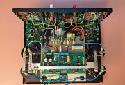
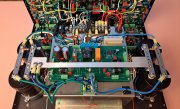
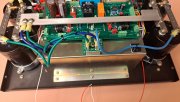
Rainy day here today, so I was able to get some more time on the Model One. I’m getting close to buttoning up the wiring, and starting the heat sinks and populating the T/O’s in the backplanes. At this point I would really appreciate fresh eyes looking at this. I have cut, tinned, PIDG’d, soldered, and sorted and routed at least 10 miles of wire so far, so I am a bit cross eyed when I try to inspect closer. I appreciate all of the suggestions. I have checked things as I put everything together, but you guys are always so good at seeing what I may have missed. I do have all of the faceplate wiring done (including the potentiometers) and will hook all of that in when the final testing gets closer. Since the buss was added, I would ask specifically whether the the 12ga wires are routed correctly including the bridge rectifier. The Excel spreadsheet is still set up for the grounding stud, so this set up made the most sense to me eliminating all of the previous 12ga wires, and incorporating the buss bar.
Thank You
Thank You


Last edited:
Vintage 700b
Chief Journeyman
Here are a few more views. I do have a question on the power switch, maybe someone can help with. The switch is an Anti-Vandal Switch, Single Pole - Single Throw Configuration (Pole Throw), Single Actuator, Flush Actuator, Illuminated, ALCOSWITCH AV25. I must admit that I have been testing switches for almost 60 years but have little experience with Latching, Anti-Vandal switching switches. I wanted to ensure that the switch is off, for starting the bring up procedure. I thought the operation of the switch would make it simple to check. Checking continuity across the switch, I cannot seem to verify operation nor a ON/OFF mode. Testing with my DMM, I do get the LED ring to illuminate, but continuity is not made/unmade as I depress the button. I got pretty frustrated with this, especially when I thought it would take a couple minutes to verify. Any help appreciated there. Do I need 24v to it to test?
Switch is wired as follows:
Red – LED Anode String
Black – LED Cathode String
Center White – Normal Open (NO) - Ground
RH White (in picture) – C - -6db setting
Thank You
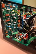


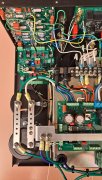

Switch is wired as follows:
Red – LED Anode String
Black – LED Cathode String
Center White – Normal Open (NO) - Ground
RH White (in picture) – C - -6db setting
Thank You


Looking good!Rainy day here today, so I was able to get some more time on the Model One. I’m getting close to buttoning up the wiring, and starting the heat sinks and populating the T/O’s in the backplanes. At this point I would really appreciate fresh eyes looking at this. I have cut, tinned, PIDG’d, soldered, and sorted and routed at least 10 miles of wire so far, so I am a bit cross eyed when I try to inspect closer. I appreciate all of the suggestions. I have checked things as I put everything together, but you guys are always so good at seeing what I may have missed. I do have all of the faceplate wiring done (including the potentiometers) and will hook all of that in when the final testing gets closer. Since the buss was added, I would ask specifically whether the the 12ga wires are routed correctly including the bridge rectifier. The Excel spreadsheet is still set up for the grounding stud, so this set up made the most sense to me eliminating all of the previous 12ga wires, and incorporating the buss bar.
Thank You
View attachment 86591View attachment 86592View attachment 86593
Check the crimp on the Blue 12AWG wire on the rectifier going to the negative cap bank. The end appears very open and not crimped.
The switch appears wired correctly.Here are a few more views. I do have a question on the power switch, maybe someone can help with. The switch is an Anti-Vandal Switch, Single Pole - Single Throw Configuration (Pole Throw), Single Actuator, Flush Actuator, Illuminated, ALCOSWITCH AV25. I must admit that I have been testing switches for almost 60 years but have little experience with Latching, Anti-Vandal switching switches. I wanted to ensure that the switch is off, for starting the bring up procedure. I thought the operation of the switch would make it simple to check. Checking continuity across the switch, I cannot seem to verify operation nor a ON/OFF mode. Testing with my DMM, I do get the LED ring to illuminate, but continuity is not made/unmade as I depress the button. I got pretty frustrated with this, especially when I thought it would take a couple minutes to verify. Any help appreciated there. Do I need 24v to it to test?
Switch is wired as follows:
Red – LED Anode String
Black – LED Cathode String
Center White – Normal Open (NO) - Ground
RH White (in picture) – C - -6db setting
Thank You
View attachment 86594View attachment 86595View attachment 86596View attachment 86597View attachment 86598
You should measure open between C and NO pins while the button is out and shorted when button pressed and latched in.
Hi John,Here are a few more views. I do have a question on the power switch, maybe someone can help with. The switch is an Anti-Vandal Switch, Single Pole - Single Throw Configuration (Pole Throw), Single Actuator, Flush Actuator, Illuminated, ALCOSWITCH AV25. I must admit that I have been testing switches for almost 60 years but have little experience with Latching, Anti-Vandal switching switches. I wanted to ensure that the switch is off, for starting the bring up procedure. I thought the operation of the switch would make it simple to check. Checking continuity across the switch, I cannot seem to verify operation nor a ON/OFF mode. Testing with my DMM, I do get the LED ring to illuminate, but continuity is not made/unmade as I depress the button. I got pretty frustrated with this, especially when I thought it would take a couple minutes to verify. Any help appreciated there. Do I need 24v to it to test?
Switch is wired as follows:
Red – LED Anode String
Black – LED Cathode String
Center White – Normal Open (NO) - Ground
RH White (in picture) – C - -6db setting
Thank You
View attachment 86594View attachment 86595View attachment 86596View attachment 86597View attachment 86598
Power switch appears to have correct wire colors and terminal locations. You confuse me however with the note about -6dB setting above? What is that about?
RH White (in picture) – C - -6db setting
Vintage 700b
Chief Journeyman
Much better!Thank You Eric
View attachment 86599
Hi JohnLooking good!
Check the crimp on the Blue 12AWG wire on the rectifier going to the negative cap bank. The end appears very open and not crimped.
I agree with Eric on that one crimp. Ensure that each crimp has the "diamond grip" ferrule feature is flattened like the other 3 terminals on the bridge are exhibiting. Check all your crimps for this appearance, very important and why PIDG terminals were specified throughout along with the proper TE AMP tooling.
Vintage 700b
Chief Journeyman
Hi Joe,
From The Excel Document for the Main Power Switch Wiring under NOTES.
It confused me as well, but I knew where it hooks up on the Power Board. The NOTES I am referring to
are at the end of the Power Switch entry in the Excel document.
___________________________________________________________________
Ground
___________________________________________________________________
LED Anode String
___________________________________________________________________
LED Cathode String
___________________________________________________________________
-6 dB setting – Channel B (Right)
___________________________________________________________________
Cut and paste error in the comments column John, I fixed in Rev AC which I will send over. Also changed the single point ground stud to the bus bar treatment.Hi Joe,
From The Excel Document for the Main Power Switch Wiring under NOTES.
It confused me as well, but I knew where it hooks up on the Power Board. The NOTES I am referring to
are at the end of the Power Switch entry in the Excel document.
___________________________________________________________________
Ground
___________________________________________________________________
LED Anode String
___________________________________________________________________
LED Cathode String
___________________________________________________________________
-6 dB setting – Channel B (Right)
___________________________________________________________________
Vintage 700b
Chief Journeyman
The switch appears wired correctly.
You should measure open between C and NO pins while the button is out and shorted when button pressed and latched in.
Thank You Eric,
I will be able to check again tomorrow. I am sure I checked every possible configuration, but will check again.
Is the "latch" a mechanical action? I don't feel any mechanical engagement in the switch, it is a soft push, and that's it. I did get some continuity when I held the button down and did not release it. That's why I wondered if I needed 24v to engage/ disengage it electrically.
The small voltage my multimeter puts out in Diode mode gently illuminates the LED ring, and that does seem to respond to the switch actuation.
Thanks again
Vintage 700b
Chief Journeyman
Thank You JoeCut and paste error in the comments column John, I fixed in Rev AC which I will send over. Also changed the single point ground stud to the bus bar treatment.
Yes, the switch is latching John and the button will recess about 0.050" when depressed and latched. That is the "ON" position. Your switch should do that. Check to ensure that the supplier you ordered it from shipped you the correct part number as there is the ON-OFF latching version and the OFF-(ON) momentary (non-latching) version of this switch.Thank You Eric,
I will be able to check again tomorrow. I am sure I checked every possible configuration, but will check again.
Is the "latch" a mechanical action? I don't feel any mechanical engagement in the switch, it is a soft push, and that's it. I did get some continuity when I held the button down and did not release it. That's why I wondered if I needed 24v to engage/ disengage it electrically.
The small voltage my multimeter puts out in Diode mode gently illuminates the LED ring, and that does seem to respond to the switch actuation.
Thanks again
Last edited:


