Billion Watt Load Bank Build

WOPL Sniffer

Veteran and General Yakker
Joined
Aug 10, 2015
Messages
11,656
Location
Minnie-Soda
Tagline
Screw it
#1
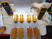
I had some input from a NASA tech (he got fired for being High), but it is loosely based on the info from Lee's schematic in the other thread. I got my 250watt 8 Ohm resistors and a couple DPDT Carling Illuminated resistors. When switched to the left, the illumination at the tip of the switch will indicate "Green" for left and right 8 ohm load, and to the right, the color goes to "Red" indicating left and right 4 ohm load. It will have connections to monitor both channels, power for the 12 volt fans and Power Switch. I ordered my Bigg ASS Heat Sinks. 12" wide and 18" Long for the base, and the 2 sides where the resistors will bolt to are 8" tall by 18" long and the top will hide any cobbling should I feel the need to cobble stuff......... The fan will bolt to the end cover and the front cover will have the switches and controls on the front with the air intake. The heat sinks will be here in a day or three. So far, I got $150 into it. I finally found a use for the 12 and 14ga wire Navo sent to me with a wire order a while back. I think I'll put in a heat disconnect (like the WOPL's) just in case. Maybe I'll airbrush it with Green Flames.

It should handle 500WPC (or 40 amps whichever comes first......)
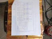


Load Bank PartsA.jpg Load Bank PartsB.jpg
 

WOPL Sniffer

Veteran and General Yakker
Joined
Aug 10, 2015
Messages
11,656
Location
Minnie-Soda
Tagline
Screw it
#2
I should have shopped around for the switches. I paid Mouser double what they are going for on other sites like Grainger/Zoro etc....
 

WOPL Sniffer

Veteran and General Yakker
Joined
Aug 10, 2015
Messages
11,656
Location
Minnie-Soda
Tagline
Screw it
#3
I forgot to add the cost of the rest of the parts, which is total of $250. At least that's what I tell the Money Manager (wife).

But, if you factor in what a good load bank is, that's friggin cheap. My Navy Math is working great.
 

Vintage 700b

Chief Journeyman
Joined
Mar 13, 2019
Messages
903
Location
Wisconsin
Tagline
Fabricator
#6
I had some input from a NASA tech (he got fired for being High), but it is loosely based on the info from Lee's schematic in the other thread. I got my 250watt 8 Ohm resistors and a couple DPDT Carling Illuminated resistors. When switched to the left, the illumination at the tip of the switch will indicate "Green" for left and right 8 ohm load, and to the right, the color goes to "Red" indicating left and right 4 ohm load. It will have connections to monitor both channels, power for the 12 volt fans and Power Switch. I ordered my Bigg ASS Heat Sinks. 12" wide and 18" Long for the base, and the 2 sides where the resistors will bolt to are 8" tall by 18" long and the top will hide any cobbling should I feel the need to cobble stuff......... The fan will bolt to the end cover and the front cover will have the switches and controls on the front with the air intake. The heat sinks will be here in a day or three. So far, I got $150 into it. I finally found a use for the 12 and 14ga wire Navo sent to me with a wire order a while back. I think I'll put in a heat disconnect (like the WOPL's) just in case. Maybe I'll airbrush it with Green Flames.

It should handle 500WPC (or 40 amps whichever comes first......)


View attachment 85641 View attachment 85642
Looking good !
Definitely Airbrushed Green Flames Perry !!!!
Perry's Billion Watt Load Bank.gif
 

WOPL Sniffer

Veteran and General Yakker
Joined
Aug 10, 2015
Messages
11,656
Location
Minnie-Soda
Tagline
Screw it
#10
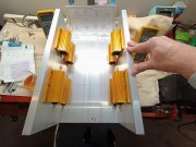
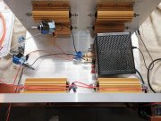
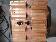
Made a bit of progress. Had to drill a shitload of holes and then tapped the holes and mounted the BAR's (Big Ass Resistors) but not before I got all that whale spooge all over. I hate that shit but I couldn't find my sheet of thermal material, so, Whale Spooge it is. I looked at my shelf from 3 feet away and just looking at it, the thermal compound jumped at me and BAMMMM, messy stuff.

I had to send the engineer from Carling a nice email (ya gotta be nice when you need stuff). The switches I got had ZERO info in the package, ZERO info on their website no markings on the switch so he sent me the proprietary drawing showing all 9 pins. Had to run and get some big boy ring terminals and some quick disconnects. With 18 pins on the 2 switches, and 16 ring terminals for the BAR's, I'll go through them quick. Now to rework the schematic we got from Lee, and find a few odds and ends of what I'm going to use for inputs and stuff. I figure a couple sets of Banana Jacks and a couple sets of BNC's for the scope and my QA401 Analyzer (I better look good at the docs so I don't blow it up testing a big amp.

Plenty of room for a power supply n stuff......


Load Build a.jpg Load Build b.jpg
 

Gepetto

Administrator
Staff member
Joined
May 15, 2011
Messages
14,153
Location
Sterling, MA
Tagline
Old 'Arn Enthusiast
#11
Made a bit of progress. Had to drill a shitload of holes and then tapped the holes and mounted the BAR's (Big Ass Resistors) but not before I got all that whale spooge all over. I hate that shit but I couldn't find my sheet of thermal material, so, Whale Spooge it is. I looked at my shelf from 3 feet away and just looking at it, the thermal compound jumped at me and BAMMMM, messy stuff.

I had to send the engineer from Carling a nice email (ya gotta be nice when you need stuff). The switches I got had ZERO info in the package, ZERO info on their website no markings on the switch so he sent me the proprietary drawing showing all 9 pins. Had to run and get some big boy ring terminals and some quick disconnects. With 18 pins on the 2 switches, and 16 ring terminals for the BAR's, I'll go through them quick. Now to rework the schematic we got from Lee, and find a few odds and ends of what I'm going to use for inputs and stuff. I figure a couple sets of Banana Jacks and a couple sets of BNC's for the scope and my QA401 Analyzer (I better look good at the docs so I don't blow it up testing a big amp.

Plenty of room for a power supply n stuff......


View attachment 85861 View attachment 85862
goes well with 2 fingers of bourbon on the side...
 

WOPL Sniffer

Veteran and General Yakker
Joined
Aug 10, 2015
Messages
11,656
Location
Minnie-Soda
Tagline
Screw it
#16
Instead of air cooling the bank, dunk the loads in oil. That is what the radio transmitter guys do.

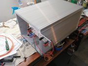
Yeah, we already went through the ghetto water heater elements and other cobbled stuff. When a customer comes over and you have shit cobbed all over your shop, it would embarrass the fuck out of me. Naw, not gonna rig stuff up although Since I'm wiring and experimenting with these DPDT 3 position (On-Off-On) Illuminated rockers and toggles, it's not tidy and it won't stay in this condition once I get the damn switch wired up to my liking, it will get tidied up. The documentation isn't really clear to me yet. The engineers just like to keep shit cryptic.
I'm just doing 4 and 8 ohm and for higher power capabilities, I may do just 8 ohms. I got eight 8 ohm 250 watt resistors. I looked at a BUNCH of skizmo's and I may just have to wing it. My end panels will be here this weekend and I need to have a concrete plan so I can lay out connections an I ran out of straight quick disconnects so the switches will get redone to get rid of the 90 degree female spades.


Loaded a.jpg Loaded b.jpg
 

wattsabundant

Chief Journeyman
Joined
Apr 26, 2011
Messages
959
Location
Central Ohio
#17
A few things to consider:
  1. Ideally, the fins would be facing inside so the fans push air across them.
  2. A switched 1:1/10:1 voltage divider that feeds the scope. The first time I did that I used 1k and 10K. WRONG! 10K and 90K or some multiple of that.
  3. You mentioned you will have two monitor switches so you can use both channels of the scope. I didn't see a second one on the drawing.
  4. Fan noise can become annoying. Thermal switches mounted on the heat sinks would provide hi/lo fan speeds. Somewhere between 50C and 60C would be a good temperature. Here's a link. Thermal switch
  5. Be aware of ground loops. Stock Phase Linear amps do not like ground loops. The two pole switches should mitigate that.
  6. Add something like a 100 ohm 50 watt resistor for use as a bleeder on DC caps.
My load bank below. Voltage divider switch on each channel located on right. Load switches are DPDT center off. Monitor switch on left feeds a Keithley 179 bench top meter to measure DC offset. Bottom, left banana jacks are a bleeder resistor. Small toggle switch to the right of bleeder resistor powers a 4" muffin fan for load resistors. IMG_0427[1].JPG
 
Last edited:

WOPL Sniffer

Veteran and General Yakker
Joined
Aug 10, 2015
Messages
11,656
Location
Minnie-Soda
Tagline
Screw it
#18
A few things to consider:
  1. Ideally, the fins would be facing inside so the fans push air across them.
  2. A switched 1:1/10:1 voltage divider that feeds the scope. The first time I did that I used 1k and 10K. WRONG! 10K and 90K or some multiple of that.
  3. You mentioned you will have two monitor switches so you can use both channels of the scope. I didn't see a second one on the drawing.
  4. Fan noise can become annoying. Thermal switches mounted on the heat sinks would provide hi/lo fan speeds. Somewhere between 50C and 60C would be a good temperature. Here's a link. Thermal switch
  5. Be aware of ground loops. Stock Phase Linear amps do not like ground loops. The two pole switches should mitigate that.
  6. Add something like a 100 ohm 50 watt resistor for use as a bleeder on DC caps.
My load bank below. Voltage divider switch on each channel located on right. Load switches are DPDT center off. Monitor switch on left feeds a Keithley 179 bench top meter to measure DC offset. Bottom, left banana jacks are a bleeder resistor. Small toggle switch to the right of bleeder resistor powers a 4" muffin fan for load resistors. View attachment 85880

That's what I like to see, very cool............. However, just like a processor being cooled on a PC, the fins are on the outside since you need the flat to fit against the heat generator, and the excess heat can radiate OUT to the environment so you can also cool that with a fan. So, I can cool the BAR's with a smaller internal fan on a thermostat set up, and if needed (I won't be operating this more than a minute or three, not developing stuff, just a quick test), I can use an external fan too but heat radiates so fins on the outside is the only correct way. If I was concerned about not being able to manage the heat, I'd resort to cobbling water heater elements and 5 gallon cans of Crisco which could double as a French Fryer. I think I will put in a small temp gauge or two as I have plenty of real estate

Great info on voltage dividers, I will definitely have a divider for L/R Scope channels. That drawing is being "loosely followed" since I have to use the switches I have and the terminals are not labeled like the drawing. Lee didn't know what switches were used so following the drawing was optional. The Mfg's don't use the same nomenclature's like c1, a1 etc.... Carling uses several types depending on the switch series....... It would have been a piece of cake if I had the switch make and model of what is in the model 250 load bank.

The switchable on/off for bleeder resistors is a great idea, I have a bleed resistor I will incorporate, same one I use for draining my bulk caps but will be internal to the load bank. I need to order a couple more switches and some of them ON OFF ON legends you have, where did you find those? I can use a hand full of them. I think I'll use momentary switches for bleeders and checking the DC offset since one brain fart on leaving one of those 2 switches in the wrong position could create a dangerous situation.


Remember this is for occasional use, not production. So, the fans won't be running all the time and heat generation won't be crazy. Full power tests would be maybe a minute just long enough to get data and THAT only takes 10 seconds.


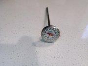
Thermometer.jpg
 
Top