
Hey all,
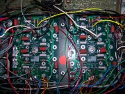
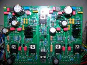
I am currently building a WOPL 700 and am having an issue with bias on the bring-up step.
All voltage test points are OK, but control board bias points test at -34V on the + side and 0.014V on the negative side with only XQ11 and XQ12 being in place. This is also with the variac outputing 60V.
Any pointers as to what is going on ?
Thanks
")
