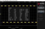
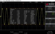
Ok Ed, gonna show my ignorance here, how do I output a signal from my scope,?
With regards to measuring rise time and/or slew rate:
Typically you would generate a square wave with a signal generator/oscillator capable of sine, square and triangular wave-forms. These signal generators are also known as function generators. The square-wave signal would go into the input of the device under test (i.e an audio amplifier) then the output would in turn go into the input of an oscilloscope. Measuring the rise time and slew rate can be done a number of ways. Your Tektronix TDS1001C-EDU has "
Measure" capabilities explained in the user manual that go into detail on rise time measurements.
NOTE: Be very careful when using square waves at frequencies above 10kHz and large signal levels (as may be required for slew rate testing) as you may damage your amplifier. Approximately 5KHz may well be more suited for slew rate tests.
I performed a number of square wave measurements a few months ago using a Tek TDS1001C-EDU with a mid 1970's vintage MITS function generator. Unfortunately, the MITS function generator had a rise time which I wasn't quite happy with around 500-600ns. Subsequently, I purchased a used Leader LFG-1310 function generator for around $100 on ebay. The Leader has a frequency range of 0.01Hz to 10MHz. (Yes that's right 0.01Hz.) Sine wave flatness (a.k.a. amplitude/level flatness): 0.01Hz to 100kHz +/-0.3dB, 100kHz to 10MHz +/-1dB. The square wave rise/fall time is 25ns or less. I am not using the Leader in any way to measure distortion since the sine wave function is only "0.5% or less" 10Hz to 50KHz which is typical of many function generators.
I will be using the Leader LFG-1310 square wave function for rise time and slew rate measurements. Additionally, I will be using the sine-wave function for frequency response tests at 1W (+0/-1dB) on Phase Linear amps. In particular series 1 amps where the frequency response was quoted as being much wider than the series 2 amps. NOTE: Since the amplitude/level flatness of the Leader is only +/-0.3dB up to 100KHz and +/-1dB 100KHz to 1MHz, I will be monitoring & adjusting the Leader output level with a DMM to ensure the level remains the same for all frequencies. Of course, this also assumes the DMM has good amplitude/level flatness as well.
I may purchase another piece of equipment which is a sine wave only signal generator. It has a range of 1Hz to 110kHz. The amplitude flatness is +/-0.02dB and the distortion is typically <.0002%. In which case, I will not monitor the output level and the THD is better than my HP 239A signal generators (a 239A is also contained in my HP 339A). The next step will be a Distortion Magnifier to improve upon my HP 339A distortion analyzer spec of .0018%. Time permitting, I will start another thread on the Distortion Magnifier and low noise oscillators/signal generators.
Many oscilloscopes have a built in fixed output square wave generator of approx. 1V or 5V for "probe compensation" with a connection on the front panel. In the case of Tektronix TDS10001C-EDU scope it is 5V @1kHz and probe compensation is discussed in the user manual.
NOTE: The Tektronix TDS1001C-EDU has a typical rise time of 8.8ns.
Lastly, as you already know, your scope also has USB output on the front panel.
Ed


