Audio Precision ATS Discussions

laatsch55

Administrator, Chief Negotiator
Staff member
Joined
Jan 14, 2011
Messages
75,849
Location
Gillette, Wyo.
Tagline
Halfbiass...Electron Herder and Backass Woof
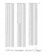
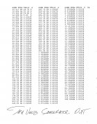
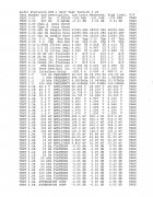
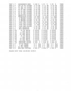
Thought I would start a thread for us who own an ATS and others that want to talk about testing with the AP.

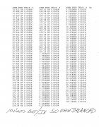
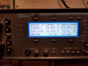
Running some cable tests....BBL
 
Great idea creating this thread Lee !
 
Last edited:
Doing some cable and voltage tests...
 
Ok...XLR to XLR....AP out to AP in , first table 650 mv output, input. From manual search on voltage this was the best THD & N figure I could get.
Carol , #20 , 2 conductor , with shield, CM, Style 2092 terminated with #2 hot to AP's convention. Switchcraft connectors.
2nd table 10 volts out, yes, that's a real figure on the low end.

Yes, the AP Passed the self test.
 

Attachments

  • AP Cable check THD & N 650 mv Gen Out20190328_19245792.jpg
    AP Cable check THD & N 650 mv Gen Out20190328_19245792.jpg
    1.9 MB · Views: 14
  • AP Cable check THD & N  10 volts Gen Out20190328_19274793.jpg
    AP Cable check THD & N 10 volts Gen Out20190328_19274793.jpg
    1.8 MB · Views: 14
Last edited:
Granted 10 volts is a LOT for #20 wire, again depending on the current, which I don't know...figure input impedance of 50 ohm...
 
Self Test results.........
 

Attachments

  • AP Self Test, 3-28-201920190328_19394243.jpg
    AP Self Test, 3-28-201920190328_19394243.jpg
    2.1 MB · Views: 6
  • AP Self Test, 3-28-2019 page 220190328_19421267.jpg
    AP Self Test, 3-28-2019 page 220190328_19421267.jpg
    1.2 MB · Views: 5
Ok...XLR to XLR....AP out to AP in , first table 650 mv output, input. From manual search on voltage this was the best THD & N figure I could get.
Carol , #20 , 2 conductor , with shield, CM, Style 2092 terminated with #2 hot to AP's convention. Switchcraft connectors.
2nd table 10 volts out, yes, that's a real figure on the low end, wire makes a difference...

Yes, the AP Passed the self test.

Time to test your test equipment Lee.

Did you back it off to 9V then 8V?
 
No...but I will.

Does that low freq figure seem out of place?
 
Ok....we were in UNBALANCED mode, in 50 ohm BALANCED mode here's what we have---
 

Attachments

  • AP Cable Test 10 volts out in 50 ohm BALANCED20190328_20151200_0001.jpg
    AP Cable Test 10 volts out in 50 ohm BALANCED20190328_20151200_0001.jpg
    1.8 MB · Views: 7
No...but I will.

Does that low freq figure seem out of place?
Yes it seems your internal signal generator is running non linear at these low frequencies and high amplitude. Not all that surprising
 
Well , I also noticed that I cannot go above 12.8 volts if the frequency is 19.9hz or below. Above 20.0hz I can go plumb to 26 volts in balanced mode and 13 in unbalanced...

So Mr. Joe.....why is it better in BALANCED mode?
 
26 volts at 20 hz...
 

Attachments

  • 20190328_202536.jpg
    20190328_202536.jpg
    2 MB · Views: 12
Evidently 10-20 hz is hard to do.......
 
And obviouisly , at the currents we're talkin here, #20 wire is fine....
 
Well , I also noticed that I cannot go above 12.8 volts if the frequency is 19.9hz or below. Above 20.0hz I can go plumb to 26 volts in balanced mode and 13 in unbalanced...

So Mr. Joe.....why is it better in BALANCED mode?
Half the amplitude of single ended Lee. 10v single ended is 5 v on each of the balanced conductors. Each out of phase by 180 degrees
 
Something to check Lee is whether the AP is rated below 20Hz for the signal generator output. Many audio analyzers are not including the HP8903B
 
Joe, I'll check on that. I have always tested frequency response to 10 hz, albeit not at those levels and didnt seem to have any issues...
 
GEN LOAD FUNCTION
Displays the equivalent ac resistive loading on selected generator
output. Intended for checking input terminations, loudspeaker
impedance, or locating shorts.
Measurement Range <l Ohm to 20 kOhm
Accuracy ±[5% +0.5 Ohm] for readings ≤ 1 kOhm.
Degrades rapidly above 1 kOhm,
or with reactive loads.
Frequency Range 20 Hz-20 kHz
Test Voltage 200 mV default. Usable from 10 mV to
generator maximum.
 

Attachments

Last edited:
Hi Lee,

This is good info to have.

A couple of observations.
I'm assuming your BW is set for 80kHz LP based on the reduction in distortion above 50kHz? You should probably run a baseline scan with the input set to "Gen" or "Gen Mon" however the ATS1 specifies it. Do that with the cables removed and then the external scans with the cables will show the difference and possibly any quality difference between cables.

My AP unit measures slightly better when its measuring internally without the cables as you would expect. I recently had a pair of XLR to RCA cables that was giving me troubles. Occasionally the Left channel distortion would randomly be like 10dB worse than the Right channel. I measured the resistance between Pin 1 & 3 and the left connector was around 2 ohms versus 0.1 ohms for the right. After resoldering the jumper wire the resistance dropped to .1 ohms and the distortion is nice and low again.
 
Back
Top