
You are using an out of date browser. It may not display this or other websites correctly.
You should upgrade or use an alternative browser.
You should upgrade or use an alternative browser.
Another PL2000 S2 rebuild
- Thread starter 74sdta
- Start date

- Joined
- Jan 14, 2011
- Messages
- 75,861
- Location
- Gillette, Wyo.
- Tagline
- Halfbiass...Electron Herder and Backass Woof
George S has done some extensive work on the 2000's , ya might peruse his threads on those..
George S has done some extensive work on the 2000's , ya might peruse his threads on those..
Yes sir! I have all of those bookmarked as well as your dchristies.
Looking forward to seeing your build.
Biggest problem with the stock unit is the limited bandwidth and inherent noise.
Cap and opamp upgrades open up the bandwidth.
Dale precision balance and volume attenuators along with off board power supply solves the noise.
Joe, Lee, and Don recommended early on to ditch the plastic RCA jacks. I resisted, but finally conceded. They do need to go.
SwitchCraft jacks are the solution, jumpered to the board with 20 AWG buss wire and eyelets on the through holes.
Eyelets are really needed on that old single sided board where the jacks were soldered.
Takes 3 diameters. I forget the size, but measured, found them on eBay. All were too long.
Made a fixture with proper thickness, cut them to length with a Dremel.
Have fun, it'll be a great preamp once completed!
Attachments
Thanks for those tips George!
Caps, resistors and opamps are on the short list for replacement. Going through the schematic vs. parts installed to create a list.
Attempted some desoldering today but it is very sketchy with these boards. Going to invest in a desoldering station.
Caps, resistors and opamps are on the short list for replacement. Going through the schematic vs. parts installed to create a list.
Attempted some desoldering today but it is very sketchy with these boards. Going to invest in a desoldering station.
Yes indeed. Fragile copper traces. You may run into issues with lifted solder pads around some of the RCA jacks due to the decades of the plastic jack flexing.
And many of the through holes elsewhere on the board are too small for the leads of upgraded caps.
Very small bits will open them up, but at expense of pad adhesion. Open them up from the copper side being careful to shave the copper and not catch and twist the pad off the board.
Working on these boards will test your skills and quality of your tools.
But, overall, they're really not too bad.
Better than the common cheap China board.
No where as nice and robust as one of Joe's heavy WOPL boards. WOPL boards make it easy!
There are issues - that is for sure.
Did a little prep work today;
Used the ambience pot as the test subject for disassembly- It looks good and test good. Will get cleaned and lubed for reinstall.
Next up was balance pot (dual gang 50k at each half) - doesn't look bad but there is 5k difference between the two sides. Will clean and reassemble but probably going to bin it and get the 100k single as used in the S1.

Going to pull the push switch assy to clean/lube.
Did a little prep work today;
Used the ambience pot as the test subject for disassembly- It looks good and test good. Will get cleaned and lubed for reinstall.
Next up was balance pot (dual gang 50k at each half) - doesn't look bad but there is 5k difference between the two sides. Will clean and reassemble but probably going to bin it and get the 100k single as used in the S1.
Going to pull the push switch assy to clean/lube.
- Joined
- Jan 14, 2011
- Messages
- 75,861
- Location
- Gillette, Wyo.
- Tagline
- Halfbiass...Electron Herder and Backass Woof
Tedious, very tedious.....
Tedious, very tedious.....
Also involves some expletives in the process. The 40+ year old parts do not like to be disturbed.
The balance pot got better after the process (now only 2k difference between L/R). The ambience pot did not fair so well. Somewhere between disassembly and reassembly it developed a hairline crack in the carbon track and now reads 22k.
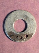
Push button disassembly.

Had issues with the old stuff, but all back together and working.
- Joined
- Jan 14, 2011
- Messages
- 75,861
- Location
- Gillette, Wyo.
- Tagline
- Halfbiass...Electron Herder and Backass Woof
Skill, determination....and something else.......I WILL NOT FAIL!!!
J!m
Veteran and General Yakker
The threat of the dumpster sometimes helps whip them in line.
- Joined
- Jan 14, 2011
- Messages
- 75,861
- Location
- Gillette, Wyo.
- Tagline
- Halfbiass...Electron Herder and Backass Woof
RTFM!!!!!
And use a thermocouple to check the temperature.
My Hakko desoldering stations are calibrated to 700 deg F on the lowest setting.
This is the setting I most often use.
Crank the heat up and it'll lift a trace right off the board.
I use this cheap clone to calibrate all my Hakko soldering and desoldering stations.
Very important!
https://www.ebay.com/itm/4043633717...NB_S8D7Qg2&var=&widget_ver=artemis&media=COPY
- Joined
- Jan 14, 2011
- Messages
- 75,861
- Location
- Gillette, Wyo.
- Tagline
- Halfbiass...Electron Herder and Backass Woof
And use a thermocouple to check the temperature.
My Hakko desoldering stations are calibrated to 700 deg F on the lowest setting.
This is the setting I most often use.
Crank the heat up and it'll lift a trace right off the board.
I use this cheap clone to calibrate all my Hakko soldering and desoldering stations.
Very important!
https://www.ebay.com/itm/4043633717...NB_S8D7Qg2&var=&widget_ver=artemis&media=COPY
Pretty cool George...won';t break ya either..
The Hakko 470 desoldering tool manual says to set the potentiometer to the lowest setting of 1, and adjust for 716 deg F.George S - great suggestion! I have the 191 clone and will definitely use it to check the temps.
The station I purchased (not hakko), ranges from 400-890F. Has 700 worked well for you?
I adjust tit to 700 deg F.
Better to be cautious because these can be turned way up for desoldering heavy assemblies.
I've found this setting at 700 works fine for those easily damaged traces on those old boards.
I also select a wide aperture nozzle that fits over the protruding lead so the nozzle melts all the solder around the lead, then pull the vacuum trigger.
Don't press the nozzle down hard or you'll do damage, just lightly rest it on the joint.
Takes some practice, but easy to desolder a entire board with no damage.
I've found it best to always leave mine on the lowest setting when doing board level work.
If I do need more heat due to a heavy ground plane, heat sink, etc, I grab the hot iron(also at 700) with the other hand and add heat to the joint with it.
The joint instantly melts and is then vacuumed.
Need to be careful, precise, and conservative.
I'm old so I use a OptiVisor so I can see the joint and do precision work. Would be a hack without it.
And lead free solder joints need leaded solder added to them first to facilitate vacuum desoldering.
They won't flow nicely into the vacuum without the added lead and new flux
Same goes for very old oxidized and corroded joints.
Add a little new leaded solder if a joint is giving you issues.
99% of the components fall or pull straight out with no board damage.
Then there's that one that needs a little new solder added to aid flow.
Have fun!