Sunnbobb
Journeyman
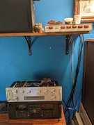
Plugging away. Work accomplished (Or is it play?):
Installed new fuse holders
Replaced the stock cord with a 16AWG NEMA 1-15P TO SJT Cable. The new cord is 4 ft and enters the cabinet through a new strain relief bushing.
Replaced old Caps with 15,000 uF/100V/105C Capacitors
Installed a new Bridge Snubber with 50A/600V bridge rectifier.
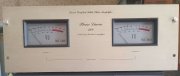
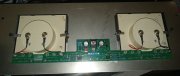
Replaced old meter light board with new LED board, together with a meter sensitivity switch.
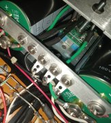
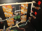
Replaced Bus Bar Assembly
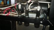
Tested all Output Transistors
Added rack handles for cool factor
-waiting for arrival of Output Relay, and that should do it for round one. (and the usual testing and bias setting)
I did have a question. The PL400 manual states the amp can draw up to 1200W at peak power. The switched outlet on the back of my PL3000 S2 preamp states 500W max. I would have thought Phase Linear would have made the switched outlet on the back of the preamp to allow for plugging the unswitchable PL amps to be plugged into them? Perhaps not a question, but an observation.
Installed new fuse holders
Replaced the stock cord with a 16AWG NEMA 1-15P TO SJT Cable. The new cord is 4 ft and enters the cabinet through a new strain relief bushing.
Replaced old Caps with 15,000 uF/100V/105C Capacitors
Installed a new Bridge Snubber with 50A/600V bridge rectifier.
Replaced old meter light board with new LED board, together with a meter sensitivity switch.
Replaced Bus Bar Assembly
Tested all Output Transistors
Added rack handles for cool factor
-waiting for arrival of Output Relay, and that should do it for round one. (and the usual testing and bias setting)
I did have a question. The PL400 manual states the amp can draw up to 1200W at peak power. The switched outlet on the back of my PL3000 S2 preamp states 500W max. I would have thought Phase Linear would have made the switched outlet on the back of the preamp to allow for plugging the unswitchable PL amps to be plugged into them? Perhaps not a question, but an observation.