Adjusting signal with resistor

Alex SE

Journeyman
Joined
Oct 10, 2021
Messages
250
Location
Sweden
Tagline
Amateur
#41
Searching the internet I've found this:
1656341973938.png
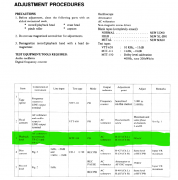
It is a part from some Onkyo deck service manual. That MTT-150 test tape is a Teac and is ANSI, which means that 245mV is correct. Since that datasheet for a CX20187 can't be found, this is the way to collect the facts. Question remains, what is the reason that Matsushita have adjusted a Dolby level about 30mV lower which is about 12-13%? Not shore if a tolerance was 5mV or 5%, but in both cases a difference is too much. Hard to believe that some engineer have seen 215mV instead of 245 but what if ...? I mean, if somebody got a bad copy of that datasheet in a paper form, or maybe 215 and 245 sounds similar in Japanese, everything is possible, isn't it?

1656344330996.png
 

Attachments

Makymak

Journeyman
Joined
Dec 6, 2021
Messages
193
Location
Where the sun meets the rocks and the sea
#42
I think that Technics calibration procedure is quite different at these models. It doesn't counting on test points on the pcb but on the output voltages. So, they don't care about the Dolby chips voltage. Somewhere on the design they made a wrong calculation. On purpose or by fault, I truly don't know. The 965 is a unique deck by many factors. The people who designed the circuits made exceptional work but the people who chose the parts buried it being a poor deck for a flagship.
 

Alex SE

Journeyman
Joined
Oct 10, 2021
Messages
250
Location
Sweden
Tagline
Amateur
#43
1. As many professionals said many times, only right way to adjust pb level is by measuring dolby output voltage. Now, if a deck is made and adjusted correctly from the factory, so that D-level matches correct output level, it would not be wrong to adjust pb level by measuring outputs. In this case it's not possible. Anyway...
What I'm wondering is how that -30mV difference on a dolby IC impacts it's functionality. I mean, SM says to adjust the output to 400mV (545mV with 200nWb/m ANSI tape), which gives about 30mV less on a dolby IC. May be that their assessment was that it is acceptable, but at the other hand, if they have build that deck from the ground, what was a problem to change a values of those 2 resistors on the output so that output is 400mV (545mV) when dolby level 180mV (245mV). After that, change the values of those 2 resistors for a peak meters and that's it. No changes in schematics, no cost difference, so no big deal.
2. Those 5218 ICs have a bad impact on the sound. Maybe that 5218 was matching their criteria. May be 5532 wasnt available in that time, don't know.
3. That AA makes a sound "digital" as some people states. In that time digital was popular, it's understandable why they made it so.

Only thing which really make me curious is point 1. Why, oh why?
 

Makymak

Journeyman
Joined
Dec 6, 2021
Messages
193
Location
Where the sun meets the rocks and the sea
#44
Maybe it's the service manual that is wrong. It happens. At theses decks (different models of the same era), the calibration procedure is the same so all the directions are quite similar and copy-paste. If you see the instructions of all this generation decks you will understand what I'm saying.

We could give a definite answer if we had a brand new 965 and could measure it's outputs. But that is impossible. Even my both 965 that weren't serviced (so at their original settings) had quite drifted due to age that their settings could not taken into account.

It's the effect of mass production. A small error in the process and a whole production line goes wrong.
 
Top