Adjust DCP timing?

BlueCrab

Journeyman
Joined
Nov 10, 2019
Messages
229
#1
So I sent this directly to Don, but decided to make it a thread instead.

I want to adjust the timing of the DCP. Currently the relay energizes in about 3 seconds (as designed). My PL4000 preamp does not output a signal for about 15 seconds, and then when it does, goes through a short 1-2 second transient where it outputs a 0.7 vdc signal. This is enough to trigger the DCP (and I'm glad it does!). So I'd like to delay the DCP for say 20 seconds to allow the PL4000 to do its transient thing and settle. Can I adjust the timing of the DCP to this longer period?
 

BlueCrab

Journeyman
Joined
Nov 10, 2019
Messages
229
#3
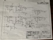
Pretty sure. I've attached a copy of the schematic of the Logic board - PL04. This PL4000 has the later version of the board which uses a quad op amp and has a timing circuit made up of Q5, Q6, R25, & C10. Both channels exhibit exactly the same behavior.

B+1 is the 30vdc direct from the power supply. Q5 & Q6 keep B+3 at zero vdc until C10 charges and then Q6 is turned on and supplies voltage to the op amp. This takes about 15 seconds. The output of the op amp goes to about +15vdc - about the midpoint of the power supply voltage. This shift from 0vdc to +15vdc is what causes the small shift in the output (about 0.7vdc) as C2 (& C4 for the other channel - both 100uF caps) charge to this midpoint voltage. The transient to 0.7vdc is short lived and quickly goes back to 0.0vdc, but it lasts long enough for the DCP to trigger.
IMG_0686.JPEG
 

Gepetto

Administrator
Staff member
Joined
May 15, 2011
Messages
13,473
Location
Sterling, MA
Tagline
Old 'Arn Enthusiast
#4
That is one of the classic problems with single supply preamps like the PL4000. The RC4136 does not properly operate until the supply voltage reaches 10V which is quite high so things get started kind of late.

You may want to experiment with an op amp like the OPA2134 (x2 on Brown Dog adapter) which is in full regulation at half that voltage, 5V.

I use the OPA134 in the WO control board for its superior sound quality plus this low turn on voltage, it minimizes turn on and off transients very nicely.

The fact that B3 comes up delayed from B1 exacerbates the condition since the midstream Class AB amp stage is up and fully powered by that B1 voltage which has no delay.
 

BlueCrab

Journeyman
Joined
Nov 10, 2019
Messages
229
#5
Thanks for the recommendation. Indeed, the single supply causes problems. And for the PL4000, each and every board seems to have input and output coupling capacitors. I'd be bothered less if there was one in the beginning and one in the end, but it seems each board has another level shift.

I'll take a look at the OPA2134 and try it if I can.
 

BlueCrab

Journeyman
Joined
Nov 10, 2019
Messages
229
#6
Going to be a challenge as the pin outs don't match. May be able to fab an adapter of some sorts. OPA4134 would be the choice.
 

laatsch55

Administrator,
Staff member
Joined
Jan 14, 2011
Messages
74,124
Location
Gillette, Wyo.
Tagline
Halfbiass...Electron Herder and Backass Woof
#7
Brown Dog makes an adapter with 2 surface mount OPA's on it that matches the 4136 pinout.
 

Gepetto

Administrator
Staff member
Joined
May 15, 2011
Messages
13,473
Location
Sterling, MA
Tagline
Old 'Arn Enthusiast
#8
Going to be a challenge as the pin outs don't match. May be able to fab an adapter of some sorts. OPA4134 would be the choice.
No, as the earlier post notes, Brown Dog makes and adapter to turn 2 OPA2134s into a RC4136 compatible quad op amp pinout.
 

BlueCrab

Journeyman
Joined
Nov 10, 2019
Messages
229
#9
Nice! I think I've found it -
Dual-to-Quad Op Amp Adapter – BrownDog 070401


But the original question still remains. 3 seconds I'm sure meets most needs, but I assume there is a simple RC network that sets the timing.
 

grapplesaw

Veteran and General Yakker
Joined
Aug 13, 2014
Messages
2,762
Location
Vancouver
Tagline
---
#10
Nice! I think I've found it -
Dual-to-Quad Op Amp Adapter – BrownDog 070401


But the original question still remains. 3 seconds I'm sure meets most needs, but I assume there is a simple RC network that sets the timing.
Talk to Don. By changing the charge capacitor you can adjust the time of engagement
 

Gepetto

Administrator
Staff member
Joined
May 15, 2011
Messages
13,473
Location
Sterling, MA
Tagline
Old 'Arn Enthusiast
#12
Why don't you shorten the preamp delay? You have the means to do that. 1 resistor change will alter the preamp delay
 

BlueCrab

Journeyman
Joined
Nov 10, 2019
Messages
229
#13
I thought of that, but it would have to be less than 3 seconds, that's not enough time for the preamp to stabilize.
 

Gepetto

Administrator
Staff member
Joined
May 15, 2011
Messages
13,473
Location
Sterling, MA
Tagline
Old 'Arn Enthusiast
#14
I thought of that, but it would have to be less than 3 seconds, that's not enough time for the preamp to stabilize.
I think it will stabilize a lot sooner than 3 seconds. The power amp stabilizes in well less than 1 second, probably 4 line cycles. Would expect the preamp to be no different.
 

Gepetto

Administrator
Staff member
Joined
May 15, 2011
Messages
13,473
Location
Sterling, MA
Tagline
Old 'Arn Enthusiast
#15
I thought of that, but it would have to be less than 3 seconds, that's not enough time for the preamp to stabilize.
The circuit with the delay of B+3 looks quite sketchy...are you sure the 2.2M resistor beats the leakage current of the 470uF cap and the base current of the first transistor?
 

wattsabundant

Chief Journeyman
Joined
Apr 26, 2011
Messages
842
Location
Central Ohio
#18
I'm late to the party again.

Yes C4 and R9 determine the relay delay time. I put a board on the test set and tacked in a 330uf cap (it measured 310 uf) in parallel with C4 (33uf) and got a delay of 28 seconds. Dropout was still instant and the cap fully discharged in less than a second. I was concerned that with such a long time constant a short AC power loss would not reset the timer properly. No problem there.

C4 could be replaced with a 270uf cap and get the desired time delay. I did try adding a 470k resistorr in series with R9 with only the stock 33uf cap and got an 18 second delay. I would not recommend changing R9 to a much higher value for the same reasson Joe mentioned about the delay in the preamp. Timing could be eratic due to the leakage of the C4 cap. It is not spec'ed out as a low leakage type.

Regardless what is changed, getting the old parts out will be problematic without a good (Hakko) desoldering tool due to the holes being plated through. Plated holes are good for reliable connections, but bad for changing parts.
 

BlueCrab

Journeyman
Joined
Nov 10, 2019
Messages
229
#19
The circuit with the delay of B+3 looks quite sketchy...are you sure the 2.2M resistor beats the leakage current of the 470uF cap and the base current of the first transistor?
I should have mentioned that as built C10 was a 100uF capacitor, not 470uF as shown on the schematic. This gave a timing of about 9 seconds. I changed it to 220uF to extend the time.

I think it will stabilize a lot sooner than 3 seconds. The power amp stabilizes in well less than 1 second, probably 4 line cycles. Would expect the preamp to be no different.
You're right, but just. Tests that I conducted this morning, the DC transient was essentially over in a little more than 2 seconds and the DCP did not trigger. To do this test I disabled the timing circuit by shorting the emitter and collector of Q5 which causes Q6 to saturate pretty much when B1 comes on.

The transient causes the needles on the meters to slam full max for a moment and then relax just before I hear the DCP relay click on. They slam again at turn off, but after the DCP has disconnected the speakers.

Don & jbeckva - Thanks for the timing info. I don't see the need to go beyond 10 seconds or so.

Here's my current plan:
  1. I've ordered the Brown Dog adapter to replace the RC4136 with two OPA2134s. The hope is this will reduce that initial transient, but even if it doesn't, the OPA2134 is a better op amp and better is the enemy of good enough.
  2. Either shorten or disable the PL4000 timing circuit. I don't see the need for it. Transient exists either way. I just want the transient over before the DCP energizes.
  3. Extend the DCP to about 6 to 10 seconds. That's more than sufficient.
  4. Plug the PL400 into a power strip and plug that power strip into the switched outlet of the PL4000. Normal operation would be to have the power switch open (PL400 off), turn on the PL4000, count to 5 potatoes, and then turn on the power strip (turning on the PL400). This would prevent all the needle banging, but if I forgot to turn off the power strip, everything would come up alright in the end. This kind of sucks, but the alternative would be to leave the PL4000 on all the time - just like Dynaco did with the PAT5 to prevent the same issue.
 

wattsabundant

Chief Journeyman
Joined
Apr 26, 2011
Messages
842
Location
Central Ohio
#20
  1. Plug the PL400 into a power strip and plug that power strip into the switched outlet of the PL4000. Normal operation would be to have the power switch open (PL400 off), turn on the PL4000, count to 5 potatoes, and then turn on the power strip (turning on the PL400). This would prevent all the needle banging, but if I forgot to turn off the power strip, everything would come up alright in the end. This kind of sucks, but the alternative would be to leave the PL4000 on all the time - just like Dynaco did with the PAT5 to prevent the same issue.
The outlet on the preamp is 2 wire. Outlet strips are generally 3 wire and I would not recommend a ground buster adaptor. The inrush current to the amp could damage the relay. I don't know if they are readily available. An alternative would be to use the preamp outlet to start a time delay relay for the amp. There are some cheap ones on ebay. There may be one that would fit inside the 4000.
 
Last edited:
Top