AC Thermal Switch Modifications ?

Mohawk

Chief Journeyman
Joined
Oct 29, 2019
Messages
716
Location
Ontario Canada
#1
I asked Joe if the backplane thermal switches on the upcoming Model ONE are DC and indeed they are..
That prompted the question:


"Did you ever publish a Mod to change the 400 / 700 thermal switches to DC ?
Any particular scheme that would be beneficial ? "


I am curious to see who has gone down this path and to what success ?
A couple of us have jumped in on the Model ONE thread but I think it deserves to stay on track.

So, The thread is open for business......

Who's first ?

M
 

grapplesaw

Veteran and General Yakker
Joined
Aug 13, 2014
Messages
2,775
Location
Vancouver
Tagline
---
#2
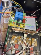
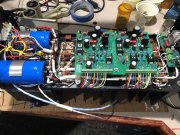
I’ve been on this for a while . I’m building a 400 with my stock of parts sitting around and they need to be used. This doesn’t mean it will be a lessor amp. I’ve added extra row of transistors again. I bolt the neat sinks on and have all new components on the back plane. i Did this once before with stunning noise results. Of coarse a Whiteoak G control board on top.
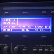
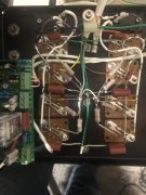
this time I’ve eliminated all ac current across the back plane.. I’ve installed a soft start which will turn the unit on and off via front panel power switch. It’s a low voltage DC signal which runs in series with the temp switch. Almost done so will see next weekend how or if it works any better IMG_6871.jpeg IMG_6870.jpeg

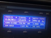
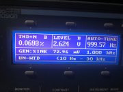
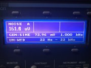
here is first go at this without the soft start. I’ve realy cleaned up the wiring across the back plane. The noise level was extremely good so hope to better it a little, we’ll see

please note it’s a lot easier to get low residual noise levels in a 400 than a 700, a dual 500 is even worse due to increasing rail voltages .

IMG_6871.jpeg IMG_6870.jpeg IMG_0437.jpeg IMG_0438.jpeg IMG_0440.jpeg IMG_0441.jpeg IMG_0432.jpeg IMG_0429.jpeg IMG_0437.jpeg IMG_0438.jpeg IMG_0440.jpeg IMG_0441.jpeg IMG_0432.jpeg IMG_0429.jpeg
 
Last edited:

wattsabundant

Chief Journeyman
Joined
Apr 26, 2011
Messages
932
Location
Central Ohio
#3
I'm not sure how Joe implemented the thermal switches. I think there is a low probability that they are used on the main DC. Very few contacts are rated for more than 32 volts DC due to arcing with the result of welded contacts. 250 VAC, no problem.

The attached PDF is a typical device we use on inverters at my day job. See page 2 for contact rating. The application uses the contact in a 24 VDC heatsink over temperature alarm. The photo is a 250 amp transfer switch using reverse parallel SCR's as the switch. The sensor is at the top of the heatsink.
 

Attachments

wattsabundant

Chief Journeyman
Joined
Apr 26, 2011
Messages
932
Location
Central Ohio
#5
The relay boards detect DC on the output and disconnect the speakers. Fast detection is critical. The 700 and 400 uses different circuits to accomplish the same goal. The higher voltages in the 700 are the reason for two different circuits.

To incorporate the thermal switches in the loop with the DC voltage detectors would get more complex and defeat design goals of fast detection, and (relatively) easy installation without drilling. Merely disconnecting the speakers with an over temperature condition does not cool down a hot amplifier. The relay board could disconnect the AC to the transformer as opposed to disconnecting the speaker. That would potentially expose the speaker to a longer exposure to DC and cause speaker damage. To incorporate all possibilities would likely require a relay with three or more contacts which takes up more space.

Summary: Every design has compromises. Trying to combine over temperature detection and DC detection into one function would likely introduce more compromises with limited benefits. I don't even want to consider some microcontroller. While I'm at it, I have no intention of putting mosfets in series with a speaker. The failure mode of a mosfet is a short drain to source. Fuses that work are too big and require a higher fault current to open fast. Small fuses arc and still damage speakers.
 

Gepetto

Administrator
Staff member
Joined
May 15, 2011
Messages
13,944
Location
Sterling, MA
Tagline
Old 'Arn Enthusiast
#6
The relay boards detect DC on the output and disconnect the speakers. Fast detection is critical. The 700 and 400 uses different circuits to accomplish the same goal. The higher voltages in the 700 are the reason for two different circuits.

To incorporate the thermal switches in the loop with the DC voltage detectors would get more complex and defeat design goals of fast detection, and (relatively) easy installation without drilling. Merely disconnecting the speakers with an over temperature condition does not cool down a hot amplifier. The relay board could disconnect the AC to the transformer as opposed to disconnecting the speaker. That would potentially expose the speaker to a longer exposure to DC and cause speaker damage. To incorporate all possibilities would likely require a relay with three or more contacts which takes up more space.

Summary: Every design has compromises. Trying to combine over temperature detection and DC detection into one function would likely introduce more compromises with limited benefits. I don't even want to consider some microcontroller. While I'm at it, I have no intention of putting mosfets in series with a speaker. The failure mode of a mosfet is a short drain to source. Fuses that work are too big and require a higher fault current to open fast. Small fuses arc and still damage speakers.
Huh???
 

mlucitt

Veteran and General Yakker
Joined
Jun 24, 2011
Messages
3,469
Location
Jacksonville, FL
#7
I'm not sure how Joe implemented the thermal switches. I think there is a low probability that they are used on the main DC.
Don, you are correct, the thermal switches do not run on the DC Rails. There is a dedicated 18VAC Toroid transformer that is rectified to give 24V Auxiliary Power on the Power Control Board. The magic is that the two Thermal Cutout Switches sit at Ground potential. If this Ground is interrupted (such as a high heat condition), the relay that controls functions on the Power Control Board unlatches.

The whole Model ONE is magical. I have ordered my second one from White Oak Audio.
 

gary33030

Journeyman
Joined
Aug 28, 2022
Messages
88
Location
Homestead, Florida 33035
Tagline
I've had Phase Linear before!
#8
Don, you are correct, the thermal switches do not run on the DC Rails. There is a dedicated 18VAC Toroid transformer that is rectified to give 24V Auxiliary Power on the Power Control Board. The magic is that the two Thermal Cutout Switches sit at Ground potential. If this Ground is interrupted (such as a high heat condition), the relay that controls functions on the Power Control Board unlatches.

The whole Model ONE is magical. I have ordered my second one from White Oak Audio.
The Amps are ready to order?
 

wattsabundant

Chief Journeyman
Joined
Apr 26, 2011
Messages
932
Location
Central Ohio
#9
I misinterpreted Joes original post. One of the leads from the transformer secondary is tapped off at the bridge rectifier AC terminal and fed to the relay board. It is half wave rectified on the board and lightly filtered so that when AC fails the relay drops out quickly. A person could wire the thermals witches in series with that connection. That would disconnect the load and should allow the amp to cool down. The only down side, which I've never seen, would be an output stage thermal runaway. The bias circuit prevents that.
 

mlucitt

Veteran and General Yakker
Joined
Jun 24, 2011
Messages
3,469
Location
Jacksonville, FL
#14
The order process is is currently in process.
The first one required 67 revisions (mostly small, typos and such) to the Wiring Chart, about a dozen Mouser orders for parts substitutions (mostly my fault) and several steep learning curves related to the new circuit board assemblies and mechanical parts sequencing.
The second one should go together quicker and with less frustration.
 
Top