BubbaH
Veteran and General Yakker
- Joined
- Mar 13, 2013
- Messages
- 3,313
- Tagline
- ---
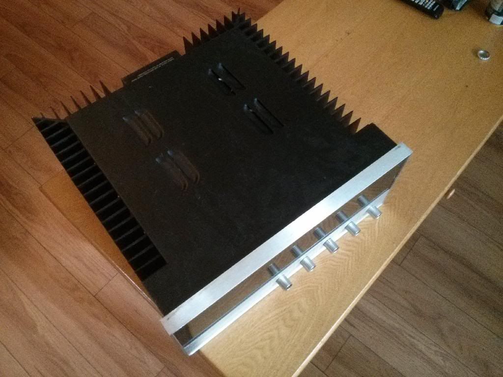
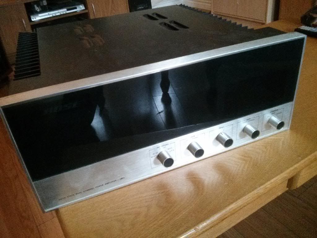
Ive heard back from my technician regarding the 1801. This is what he had to say
Left channel - 0.1V measured across the output. This is acceptable.
Right channel
DC offset of 34.5V measured across output. This measurement was obtained with the amp plugged in to 120V AC and not turned on.
Q6, Q7 and Q8 are bad.
Service Bulleting #13A recommends changing R3 from a carbon resistor to a ceramic resistor and raising it off the board. It also asks that you check value as it tends to decrease in value with heat and will stress C2 and CR15 causing them to fail. It also requests that you replace R2 with an 8.2kohm resistor from the present 3kohm. All of this has been done, however, the R3 replacement is still a carbon type. In addition the resistance has dropped from 3Kohm to about 700 ohms. The board is burned where this resistor connects to the trace. I will be changing this resistor to a ceramic type. Although C2 and CR15 check OK, because the value of R3 has decreased I will be replacing them as well.
Bulletin #17
The schematic identifies a 2N6175 in the location of Q3 which would be suspect with a + DC reading on this channel's output. Although I cannot locate a datasheet for this transistor, it checks OK. In checking the board, this transistor is not labelled as a 2N6175, nor an MMPS U10 as indicated in this bulletin. This bulletin recommends that if this board has an MMPS U10 in the location of Q3, R11 should be changed from a 1.5Kohm resistor ( as verified currently ) with a 1.8 kohm.
This bulletin recommends the R13 bias pot be replaced with a new one that has not been sealed with glyptol ( becomes conductive as it dries due to heat ). This bias pot appears to have been changed.
It also recommends a 10kohm thermistor be installed across R11 which is not installed presently. It recomments that this themistor be affixed to the heat sink above it with insulating mylar and heat sink compound. As the transistor in the location of Q3 checks out OK, and does not appear to be an MMPS U10, I recommend that we perform the update anyway.
Bulletin Pro-81-001. Your amplifier currently uses the original BOSe part no. 102433. I am currently in the process of checking these on the right channel board. If I find any of these are bad, I will be replacing the faulty ones with the new part no. referenced.
Regarding the bulletins, I will proceed to update both the right and left channels based on what I have seen with the right channel. As stated earlier, I want to perform additional checks to ensure there are no other failed components.
Im happy I have found someone who can actually fix stuff.


