You are using an out of date browser. It may not display this or other websites correctly.
You should upgrade or use an alternative browser.
You should upgrade or use an alternative browser.
700II resistors/diodes
- Thread starter SG700II
- Start date
J!m
Veteran and General Yakker
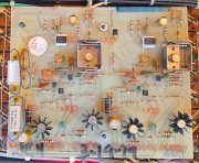
Those little things you circled look like diodes to me.
The big ceramics are resistors.
The big ceramics are resistors.
SG700II
New Around These Parts
- Joined
- May 29, 2024
- Messages
- 29
Correct, im trying to figure out which diodes these are on the schematic, to inturn know their type.Those little things you circled look like diodes to me.
The big ceramics are resistors.
- Joined
- Jan 14, 2011
- Messages
- 75,912
- Location
- Gillette, Wyo.
- Tagline
- Halfbiass...Electron Herder and Backass Woof
D1 is a 1N4744, D101 is a 1N4148
- Joined
- Jan 14, 2011
- Messages
- 75,912
- Location
- Gillette, Wyo.
- Tagline
- Halfbiass...Electron Herder and Backass Woof
If you demount them they will be marked..
SG700II
New Around These Parts
- Joined
- May 29, 2024
- Messages
- 29
If you demount them they will be marked..
Perfect, thank you for the info and tip.D1 is a 1N4744, D101 is a 1N4148
- Joined
- Jan 14, 2011
- Messages
- 75,912
- Location
- Gillette, Wyo.
- Tagline
- Halfbiass...Electron Herder and Backass Woof
You are welcome...
MarkWComer
Veteran and General Yakker
- Joined
- Nov 1, 2014
- Messages
- 3,520
- Location
- Gaston, SC
- Tagline
- Victim of the record bug since age five
I thought it strange that they never drilled holes for the wire connections at the bottom of the boards.
Seems a bit tenuous to me, an opportunity for failure.
Seems a bit tenuous to me, an opportunity for failure.
J!m
Veteran and General Yakker
Gotta keep those repair techs employed.
SG700II
New Around These Parts
- Joined
- May 29, 2024
- Messages
- 29
Thank you very much. This clears up my confusion.The components you're looking for are R1, R2 (2.4K, 5W) and D1, D2 (Both 1N4744) as shown in following schematics and diagram from service manual:


Sunnbobb
Journeyman
Same parts I found "browned" on the PL36 board I just replaced with a WOPL board. I replaced the parts, but they still heated up to an unacceptable level. Keep track of the orientation of the Diodes. I seem to remember having a question about that with the PL schematic vs what I found installed. May have been a mistake of a previous tech, not sure.
SG700II
New Around These Parts
- Joined
- May 29, 2024
- Messages
- 29
I plan to eventually do a full WOPL conversion. Starting little by little.Same parts I found "browned" on the PL36 board I just replaced with a WOPL board. I replaced the parts, but they still heated up to an unacceptable level. Keep track of the orientation of the Diodes. I seem to remember having a question about that with the PL schematic vs what I found installed. May have been a mistake of a previous tech, not sure.
grapplesaw
Veteran and General Yakker
SG700II
New Around These Parts
- Joined
- May 29, 2024
- Messages
- 29
I read about this in another site, but did not have all the info this bulletin gives. Thank you. I will consider it, however I already ordered the 2.4kohm. Perhaps in a few months, but then again, im going to eventually do WOPL.I’d suggest you upgrade the 2.3k 5 watt resistors to 7.5k 5 watt and change the ic’s to lf351 type
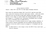
here is the PL docView attachment 81717
Last edited:
wattsabundant
Chief Journeyman
SG700II
New Around These Parts
- Joined
- May 29, 2024
- Messages
- 29
I’d suggest you upgrade the 2.3k 5 watt resistors to 7.5k 5 watt and change the ic’s to lf351 type
here is the PL docView attachment 81717
Attached is the service manual. see the bulletins. It wouldn't hurt to add a small electrolytic cap, say 100uf/25 volt and a 0.1uf film cap in parallel with the zeners.
Ordered the caps, opamps, 7k5 5w resistors.
Thank you
mlucitt
Veteran and General Yakker
Phase Linear chose to reduce the control board voltage from 100V to 15V with large power resistors and Zener diodes. This is not optimal as shown by the "browning" of the circuit board. The White Oak Audio Rev G1 Control Board uses two +15V and -15V precision power supplies (dedicated power transistors with large heat sinks fed by voltage regulators and Zener diodes) for each channel. This ensures the OPAMPs and other related components have constant and reliable DC power available regardless of supply voltage or circuit loading.
Last edited:
J!m
Veteran and General Yakker
“Using what we refer to as… the right way…”


