700II On/Off Switch ?

SG700II

New Around These Parts
Joined
May 29, 2024
Messages
25
#1
Noticed this morning, that the on/off switch has no effect on the amplifier. Its always on.

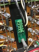
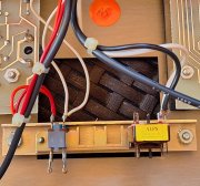
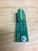
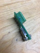
The switch itself feels normal, the connections in the back look normal.

Will have time to follow the wires (black/white) back into the amp this sunday, to see what I find.

Anyone have any tips on what might be going on here ? 20240527_115409.jpg
 

SG700II

New Around These Parts
Joined
May 29, 2024
Messages
25
#6
Replace the switch (you have no choice on that), install a “quencharc” to absorb the switch arcing…
View attachment 81763
So basically, the welding which others are talking about, is within the switch itself ?

Which switch do you recommend ? part number ?

How do I install the film cap ? one lead on the black, one on the white ?
 

marcok

Chief Journeyman
Joined
Jun 9, 2014
Messages
1,015
Location
Milan Italy
Tagline
I'm very curious about any tech item
#7
You must use 0,01 uF 400 V for 120 VAC or 0.022 uF 630 V for 230 VAC .( typical values )
Anyway after replacing the power switch , it's better to use a 16 A relay in series or Don's circuit .
I use a 16A relay on PL 4000 ( with capacitor ) to power PL 700B on .
and an external power strip with switch for Yamaha CA 2010 ( preamp section ) and PL 700.
Ciao
Marco
 

Hexis22

Chief Journeyman
Joined
Dec 28, 2022
Messages
571
Location
Wisconsin
#8
So basically, the welding which others are talking about, is within the switch itself ?

Which switch do you recommend ? part number ?

How do I install the film cap ? one lead on the black, one on the white ?
Robust overkill solution for power on/off 700 switch includes the following mechanical switch and Triac board (no capacitor required):
Switch:
https://www.ebay.com/itm/364889437590

Triac:
Contact Don @wattsabundant for availability

See my build thread for details: https://forums.phxaudiotape.com/threads/700-series-ii-build.11023/
 

SG700II

New Around These Parts
Joined
May 29, 2024
Messages
25
#9

wattsabundant

Chief Journeyman
Joined
Apr 26, 2011
Messages
883
Location
Central Ohio
#11
There is a replacement switch available, but I think it requires a new mounting bracket that is also available. I'll try to look it up.

I've got a small pcb with a triac (solidstate switch) that is controlled by the main power switch. The existing power switch controls the triac which switches the AC off and on. It's rated at 40 amps but can withstand 400 amp surge currents. I documented 145 amp surge currents on a 700B during development. Like the relay boards I sell, the triac board mounts without any drilling. It uses the bottom screw that holds the driver board. The triac's tab is electrically isolated and uses the chassis as a heat sink. Attached are some photos.

I've threatened to list the board on EBAY. Just haven't got around to it. Anyone interested in learning more can see an extensive thread at Audio Karma called unobtanium power switch.

About 20 years ago I used a similar concept to automatically sequence several AC outlets to start up the power amps last. Like so many things it never went to market.

The quench arc mentioned above helps stop the contact arcing and extends the life of the switch. It's not needed, and not recommended if the triac board is installed. The reason is the quench arc allows a tiny current to flow which puts a small voltage on the transformer. There is a potential shock hazard to any one working on the amp who is not aware of the quench arc. For that matter the same is true when a snubber cap is put across the switch.
 

Attachments

MarkWComer

Veteran and General Yakker
Joined
Nov 1, 2014
Messages
3,328
Location
Gaston, SC
Tagline
Victim of the record bug since age five
#13
The reason is the quench arc allows a tiny current to flow which puts a small voltage on the transformer. There is a potential shock hazard to any one working on the amp who is not aware of the quench arc. For that matter the same is true when a snubber cap is put across the switch.
Yeh, there is a shortfall to the quencharc. Ceramic discs are pretty common in many power switches, all of them leak a bit of current. ALWAYS unplug something you’re servicing!
 

mlucitt

Veteran and General Yakker
Joined
Jun 24, 2011
Messages
3,412
Location
Jacksonville, FL
#15
These PL400 and PL700 Series II latching power switches are known as TV-5 (5A steady rated, 78A peak) or TV-8 (8A steady rated, 117A peak).
These switches were designed for tube televisions that had high inrush current demands, and were approved and rated by Underwriter's Laboratory (UL). You can find them on ebay:
https://tinyurl.com/5evnj254

You can also use both sets of contact terminals on your replacement switch if it is a DPDT type. This shares the current between both sets of contacts and helps the lengthen the life of the switch. By using two Vishay "Safety" X440 AC-rated .01uF ceramic capacitors (Mouser P/N 72-VY2103M63Y5US63V0) across the contacts, you will have minimum arcing.
 

SG700II

New Around These Parts
Joined
May 29, 2024
Messages
25
#16
These PL400 and PL700 Series II latching power switches are known as TV-5 (5A steady rated, 78A peak) or TV-8 (8A steady rated, 117A peak).
These switches were designed for tube televisions that had high inrush current demands, and were approved and rated by Underwriter's Laboratory (UL). You can find them on ebay:
https://tinyurl.com/5evnj254

You can also use both sets of contact terminals on your replacement switch if it is a DPDT type. This shares the current between both sets of contacts and helps the lengthen the life of the switch. By using two Vishay "Safety" X440 AC-rated .01uF ceramic capacitors (Mouser P/N 72-VY2103M63Y5US63V0) across the contacts, you will have minimum arcing.
Thank you very much
 
Top