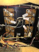
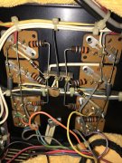
I have 5 or 6 unconverted amps in the closet so thought I'd play around with one to see if I could get it going non-WOPL mode. First thing I noticed was repair work replaced all the outputs on the left side of the amp and all the emitter resistors as well. With ceramic. Then I noticed that each channel is supposed to have a 10 ohm resistor that you set bias across. This one only has a single 10 ohm on the repaired side. Another 1 ohm resistor coming off the attached point for emitter resistors on the repaired side. On the un-repaired side both resistors are 1 ohm coming off the emitter resistor connect point. I've attached photos of both sides and the service manual. Are divergences between the manual and the amp like that common?

You are using an out of date browser. It may not display this or other websites correctly.
You should upgrade or use an alternative browser.
You should upgrade or use an alternative browser.
400 Series II (standard) repair
- Thread starter FredR
- Start date
- Joined
- Jan 14, 2011
- Messages
- 75,466
- Location
- Gillette, Wyo.
- Tagline
- Halfbiass...Electron Herder and Backass Woof
Not really Fred, I've never seen that one..
- Joined
- Jan 14, 2011
- Messages
- 75,466
- Location
- Gillette, Wyo.
- Tagline
- Halfbiass...Electron Herder and Backass Woof
Looks like all the bias resistors are brown-black-black....
Brown black black with silver gold. Silver brings them down to 1 ohm. Confirmed by measurement.
Looks like all the bias resistors are brown-black-black....
mlucitt
Veteran and General Yakker
Brown (1) - Black (0) - Black (x1) is 10 Ohms. The fourth band is Silver and gives a 10% tolerance. The reference I have (IEC 60062) shows the fifth band may indicate a temperature coefficient (ppm/K) and will be Brown (100 ppm), Red (50 ppm), Orange 15 ppm), or Yellow (25 ppm). I believe you have 100 Ohm, 10% Tolerance, 25 ppm Temperature Coefficient resistors in you unit. They often measure less than that due to age and heat cycling.
If you have another standard that shows a fifth band with a different meaning, I am all ears. Not saying you are wrong, at all. Mine were just like yours and measured low as well.
If you have another standard that shows a fifth band with a different meaning, I am all ears. Not saying you are wrong, at all. Mine were just like yours and measured low as well.
Last edited:
WOPL Sniffer
Veteran and General Yakker
That's why we wopl them mothers.... TICK TICK TICK

Was using this calculator:
https://www.allaboutcircuits.com/tools/resistor-color-code-calculator/
It does list an exception for old 5 band resistors, but these measure 1 ohm, same as calculator. Will double check.
https://www.allaboutcircuits.com/tools/resistor-color-code-calculator/
It does list an exception for old 5 band resistors, but these measure 1 ohm, same as calculator. Will double check.
- Joined
- Jan 14, 2011
- Messages
- 75,466
- Location
- Gillette, Wyo.
- Tagline
- Halfbiass...Electron Herder and Backass Woof
Outputs still in?
MarkWComer
Veteran and General Yakker
- Joined
- Nov 1, 2014
- Messages
- 3,520
- Location
- Gaston, SC
- Tagline
- Victim of the record bug since age five
If not for out of tolerance components,That's why we wopl them mothers.... TICK TICK TICK
View attachment 34859
at least for obsolete ones that aren’t available anymore.
The RCAs and first row of MJ21196G are in. Stopped there since I could not adjust bias.
Outputs still in?
Just doing this for fun. Definitely will not be hooked up to the 9Kappas.
That's why we wopl them mothers.... TICK TICK TICK
View attachment 34859View attachment 34859View attachment 34859View attachment 34859View attachment 34859View attachment 34859
- Joined
- Jan 14, 2011
- Messages
- 75,466
- Location
- Gillette, Wyo.
- Tagline
- Halfbiass...Electron Herder and Backass Woof
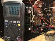
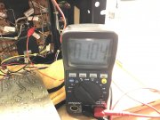
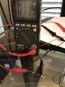
Desopder one of those 1 ohmers and check it .
Good call Lee. 11.4 ohms out of circuit.
Desopder one of those 1 ohmers and check it .
Attachments
- Joined
- Jun 11, 2010
- Messages
- 6,902
- Location
- Powhatan, Virginia, United States
- Tagline
- WassupYa Mang?
2nd that motion. I have a 400 in the dirty sock... lol, yep figured that (just saw your reply). B to E short somewhere in the outputs likely.Desopder one of those 1 ohmers and check it .
- Joined
- Jun 11, 2010
- Messages
- 6,902
- Location
- Powhatan, Virginia, United States
- Tagline
- WassupYa Mang?
Another question. The interconnect diagram 2-7 shows only two 10 ohm resistors, but this amp contains four. Maybe Ed can help.
Each channel should have a 10 ohm'er for each rail +/-.
- Joined
- Jun 11, 2010
- Messages
- 6,902
- Location
- Powhatan, Virginia, United States
- Tagline
- WassupYa Mang?
In the photo which two of the four are redundant?
None. For each channel you have two - one on each rail.

- Joined
- Jan 14, 2011
- Messages
- 75,466
- Location
- Gillette, Wyo.
- Tagline
- Halfbiass...Electron Herder and Backass Woof
None Fred. Ya need all 4. Positive and negative output each need one...