But I want to address the small offset.
The real question is What control board do you have? Because your amplifier is the venerable PL700, you have the fully adjustable PL0171 board.
Looking at the picture of your control board, the bottom potentiometer is R7, the potentiometer next to it is R17. These are on the Left Channel.
Here are the instructions for reducing the Output Offset to the factory spec, "about +75mV of DC voltage at the output terminals." Lower is better.
1. With the amplifier off, disconnect all speaker and Input Cables.
2. Gain access to the control board by dropping the Faceplate onto a soft surface.
3. Connect your Multi meter to the Left Channel Speaker Binding Posts.
4. Ensure switch on the rear of the chassis to is set to "Normal."
5. Rotate the Left volume control fully counter-clockwise.
6. Turn the amplifier on.
7. Rotate the Left Channel potentiometer R17 to get zero mV, or the lowest reading on the Multi meter.
8. Rotate the Left volume control fully clockwise.
9. Rotate the Left Channel potentiometer R7 to get zero mV, or the lowest reading on the Multi meter.
10. Repeat this until the Output Offset remains zeroed at both the full clockwise and counter-clockwise positions of the volume control.
11. Repeat steps 3-10 for the Right Channel.
While you are in there... Adjust the Bias. Easy to do if you have two small insulated alligator clips, attach them to each end of the resistor before turning on the amplifier. Then turn the amplifier on and let it warm up for 15 minutes.
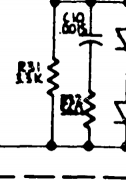
1. Measure the DC Voltage drop across R47 (I think the Service manual calls out R40), this is the 10 Ohm 1/4W resistor on the back of the amplifier just to the left of the control board.
2. Locate R36 (the potentiometer with the white wheel on the left side of the control board) and turn it slightly to get a reading of +350mV.
3. Turn the amplifier off and locate R47 on the Right channel of the back of the amplifier, in the same position as R47 on the Left Channel.
4. Attach the alligator clips and turn the amplifier on.
5. Locate R36 (the potentiometer with the white wheel on the right side of the control board) and turn it slightly to get a reading of +350mV.
Congratulations, you are done.

 1.6 MB Views: 31
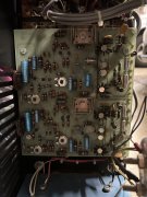 1.4 MB Views: 32