PL 700 version

timfountain

New Around These Parts
Joined
Feb 10, 2024
Messages
11
#1
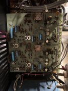
Apologies for the newbie question. I have been given a PL 700, with a small DC offset on one channel (180mv). Both channels can make rated power output into my test load without distortion. But I want to address the small offset. The question is which version of the PL 700 is this?

Thanks in advance.

PS power switch is new, as the older turn knob had fallen to bits...
 

Attachments

mlucitt

Veteran and General Yakker
Joined
Jun 24, 2011
Messages
3,469
Location
Jacksonville, FL
#5
But I want to address the small offset.
The real question is What control board do you have? Because your amplifier is the venerable PL700, you have the fully adjustable PL0171 board.
Looking at the picture of your control board, the bottom potentiometer is R7, the potentiometer next to it is R17. These are on the Left Channel.

Here are the instructions for reducing the Output Offset to the factory spec, "about +75mV of DC voltage at the output terminals." Lower is better.
1. With the amplifier off, disconnect all speaker and Input Cables.
2. Gain access to the control board by dropping the Faceplate onto a soft surface.
3. Connect your Multi meter to the Left Channel Speaker Binding Posts.
4. Ensure switch on the rear of the chassis to is set to "Normal."
5. Rotate the Left volume control fully counter-clockwise.
6. Turn the amplifier on.
7. Rotate the Left Channel potentiometer R17 to get zero mV, or the lowest reading on the Multi meter.
8. Rotate the Left volume control fully clockwise.
9. Rotate the Left Channel potentiometer R7 to get zero mV, or the lowest reading on the Multi meter.
10. Repeat this until the Output Offset remains zeroed at both the full clockwise and counter-clockwise positions of the volume control.
11. Repeat steps 3-10 for the Right Channel.

While you are in there... Adjust the Bias. Easy to do if you have two small insulated alligator clips, attach them to each end of the resistor before turning on the amplifier. Then turn the amplifier on and let it warm up for 15 minutes.
1. Measure the DC Voltage drop across R47 (I think the Service manual calls out R40), this is the 10 Ohm 1/4W resistor on the back of the amplifier just to the left of the control board.
2. Locate R36 (the potentiometer with the white wheel on the left side of the control board) and turn it slightly to get a reading of +350mV.
3. Turn the amplifier off and locate R47 on the Right channel of the back of the amplifier, in the same position as R47 on the Left Channel.
4. Attach the alligator clips and turn the amplifier on.
5. Locate R36 (the potentiometer with the white wheel on the right side of the control board) and turn it slightly to get a reading of +350mV.

Congratulations, you are done.
 

timfountain

New Around These Parts
Joined
Feb 10, 2024
Messages
11
#6
The real question is What control board do you have? Because your amplifier is the venerable PL700, you have the fully adjustable PL0171 board.
Looking at the picture of your control board, the bottom potentiometer is R7, the potentiometer next to it is R17. These are on the Left Channel.

Here are the instructions for reducing the Output Offset to the factory spec, "about +75mV of DC voltage at the output terminals." Lower is better.
1. With the amplifier off, disconnect all speaker and Input Cables.
2. Gain access to the control board by dropping the Faceplate onto a soft surface.
3. Connect your Multi meter to the Left Channel Speaker Binding Posts.
4. Ensure switch on the rear of the chassis to is set to "Normal."
5. Rotate the Left volume control fully counter-clockwise.
6. Turn the amplifier on.
7. Rotate the Left Channel potentiometer R17 to get zero mV, or the lowest reading on the Multi meter.
8. Rotate the Left volume control fully clockwise.
9. Rotate the Left Channel potentiometer R7 to get zero mV, or the lowest reading on the Multi meter.
10. Repeat this until the Output Offset remains zeroed at both the full clockwise and counter-clockwise positions of the volume control.
11. Repeat steps 3-10 for the Right Channel.

While you are in there... Adjust the Bias. Easy to do if you have two small insulated alligator clips, attach them to each end of the resistor before turning on the amplifier. Then turn the amplifier on and let it warm up for 15 minutes.
1. Measure the DC Voltage drop across R47 (I think the Service manual calls out R40), this is the 10 Ohm 1/4W resistor on the back of the amplifier just to the left of the control board.
2. Locate R36 (the potentiometer with the white wheel on the left side of the control board) and turn it slightly to get a reading of +350mV.
3. Turn the amplifier off and locate R47 on the Right channel of the back of the amplifier, in the same position as R47 on the Left Channel.
4. Attach the alligator clips and turn the amplifier on.
5. Locate R36 (the potentiometer with the white wheel on the right side of the control board) and turn it slightly to get a reading of +350mV.

Congratulations, you are done.
Thank you! I will be trying that this weekend...

Cheers

- Tim
 

timfountain

New Around These Parts
Joined
Feb 10, 2024
Messages
11
#7
Ok, so I finally got around to messing with the beast. The left channel adjusted fine, both offset and bias were easy to reset to factory. The problem is the right channel. The offsets adjusted fine, but when I went to adjust the bias, I got a 0 V reading across the 10 ohm resistor, not the ~350 mV that I was expecting. The schematic is borderline illegible for the PL0171 board, and I am struggling to determine where to start, as working on this thing gives me the chills. I suspect the pre-drivers which look to be RCA40414 and RCA40327. But the schematic doesn't appear to match the pre-driver transistors on this board version - see photos upthread. I don't believe anyone has been in here and fiddled as both sides are the same and all looks unmolested on the underside. Thoughts much appreciated.
 

laatsch55

Administrator,
Staff member
Joined
Jan 14, 2011
Messages
74,825
Location
Gillette, Wyo.
Tagline
Halfbiass...Electron Herder and Backass Woof
#8
That board has the bias transistors on the board not the backwall of the chassis, check gain on bias transistors...
 

mlucitt

Veteran and General Yakker
Joined
Jun 24, 2011
Messages
3,469
Location
Jacksonville, FL
#10
I got a 0 V reading across the 10 ohm resistor
This is an indication of a bad R47 10 Ohm resistor in the Right Channel. I have seen several of these 10 Ohm resistors physically cracked (electrically open) in the middle and this is due to the heat stress in that location.
We typically upgrade this antique 1/4 Watt 10% Carbon resistor to a new 1/2 or 1 Watt 1% Metal Film resistor.

You can check the resistance across the resistor when the amplifier has been turned off and unplugged for 15 minutes. That should alleviate your "chills". You may not measure exactly 10 Ohms due to multiple current paths, but it should be close and definitely not Infinite Ohms (open). It should also match the Left Channel.

The other option is a bad R6 (MPS5172) NPN transistor in the Right Channel as Lee suggested. Of course, those are no longer available, but Phase Linear changed R6 to a 2N3403 in the PL700B. Today, we use a 2N5088 as a Bias transistor because they are widely available.
 
Last edited:

timfountain

New Around These Parts
Joined
Feb 10, 2024
Messages
11
#12
I'm still struggling with the left channel. Nothing that I have done has changed the lack of any bias current across the 10-ohm resistor (R47). Both resistors check out fine, (they read ~11 ohms), all the transistors in the bias section have been replaced, but the old ones tested fine. All small signal diodes (1n4148) have been replaced and still, nothing on that channel. I do get 52 mv on one of the 10 ohms resistors and 2-3 mv on the other. I have measured every resistor on the LHS channel, lifting legs where necessary, and all checked out. I am out of ideas. Any brainwaves from my learned friends here? Has anyone seen the electrolytics go bad? They test a little high but ESR is still good on all 5 of them on that channel.
 
Last edited:

George S.

Veteran and General Yakker
Joined
Feb 18, 2020
Messages
5,021
#14
Print the data sheets for the voltage regulators and carefully test them. No probe slips or you'll have more issues with the amp.
Should be schematics in the PDF files
 

timfountain

New Around These Parts
Joined
Feb 10, 2024
Messages
11
#15
Broken trace?

I was having fits with a simple Micro Seiki power supply that ended up being a broken trace…
I was thinking that was well as some of the traces are very thin and wind around the board, but so far I've buzzed them all and they seem ok. It's really weird as this is not my first amp R&R. I've got an MS EE and 40 years of building and repairing electronics, mainly amps, radios and test equipment - I work for a little German company in Munich called Rohde & Schwarz... In my day job I work at slightly higher frequencies, up to 44 GHz... Wires are optional!

I am getting worried, as I am running out of options. It's very weird. One thing that is really limiting progress is the lack of a legible schematic for the early PL0171 board. The one I have is not all that useful. Any hints of where to find a decent one would be most welcome...

My next port of call is to replace all the caps both electrolytic and the others... The order is coming in from Mouser tomorrow, but as I said I am not confident as they all tested fine, on both a capacitance meter and a specialist ESR meter for the Electrolytics. I'm not into replacing things that appear to be in-spec...
 

timfountain

New Around These Parts
Joined
Feb 10, 2024
Messages
11
#16
Print the data sheets for the voltage regulators and carefully test them. No probe slips or you'll have more issues with the amp.
Should be schematics in the PDF files
Agreed on the probe slips, I am super careful around the 'beast'! As I said above, one factor limiting progress is the lack of a legible schematic.
 

timfountain

New Around These Parts
Joined
Feb 10, 2024
Messages
11
#18
If you look at my post # 11 you'll find the 700/700B service manual. Did you see page 10?
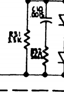
I did, but unfortunately the copy is no good. It's illegible. Not blaming you, but it's not useful. See this as an example of how it renders for me...

1714619877345.png

ETA - Just looked at page 10, maybe this will work... Thanks!
 
Last edited:

mlucitt

Veteran and General Yakker
Joined
Jun 24, 2011
Messages
3,469
Location
Jacksonville, FL
#20
Don, the manual you posted is the later version from February 1981. It is a pretty conventional pdf digitized scan of the original document. I think the original June 1976 version of the PL700/PL700B Service Manual might have a slightly better scan of the PL0171 control board. I posted it here.
 

Attachments

Top