Richard's PL Beastie Rework

jbeckva

Admin/Server Dude MAA Guy
Staff member
Joined
Jun 11, 2010
Messages
6,922
Location
Powhatan, Virginia, United States
Tagline
WassupYa Mang?
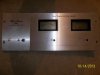
Figured I'd start with a new thread. Got Richard's amp in last night. Uh oh... Looks like the shipping gorilla found a victim!

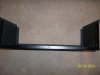
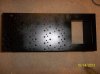
Lee the metal maniac will probably have a few suggestions on this, so I'll wait for input before doing anything. Looks like we'll need to do some chassis bending somewhere in the workflow here. :banghead:

20131012_205028.jpg20131012_204922.jpg20131012_204816.jpg


Getting ready to variac... Found one blown rail fuse (pretty "hot" blow at that... )

20131012_220233.jpg

Caps... hmmm.... They are the traditional 9.8K's but obviously newer in manufacture than normal. Lee I think we should still go with the 22's, as the "stock" ones generally don't have quite the gusto needed.

More as (gulp) power is applied... hehe.

20131012_220538.jpg
 
I have a series 1 chassis he can have too.....

Damn nice of you Lee - that'll be a fantastic beginning to the clean up of this guy.

Hey Jer. I've just gotta see a photo of the ass end of the transformer with the big bolt sticking out the backside when you get a chance - with the cover removed of course. Hopefully Lee hit the head on the nail on the head with his suggestion that it was used as a way to suspend the amp in a rack.

Will Do!

So the Variac test was interesting... That current wanted to fire "right up" even with the dial turned way down... Something obviously up with that. Isolated THAT issue to the right side, positive rail since after disconnecting power the negative charge on the caps stayed fairly steady... but the charge on the positive side went straight to zero. Right side... pulled both rail fuses and excessive current draw disappeared.

Troubleshot a lil.. appears to be a weak/half short C25 on the backwall that wants to yank the positive rail to ground when it has a lil voltage coming through it.

Fascinating "patient" so far.. hehe. We'll see what's next here shortly...

I'm glad to hear that you've got a good start on figuring this one out. Sure sounds like something is shorted. Good luck! We will all be listening to your progress.
 
Man this is just great! I wish I was as smart as you fellas. I'm a decent fabricator in steel( I'm in the garage right now building a custom 2"x72" belt grinder/4 wheel bench grinder/disk sander, mostly out of scrap my buddies and I have laying around). I can fake it O. K. doing woodwork. But electrical, especially electronics, I'm pretty much clueless. This is a great community here. I'm also all about "pay it forward", I always try to help out younger/less experienced folks who are trying to build old hot rods. I'm pretty bad about hoarding old car parts, never sell anything, but I won't hesitate to "donate" stuff to a friend or even a stranger in need. Karma maybe?
 
Man this is just great! I wish I was as smart as you fellas. I'm a decent fabricator in steel( I'm in the garage right now building a custom 2"x72" belt grinder/4 wheel bench grinder/disk sander, mostly out of scrap my buddies and I have laying around). I can fake it O. K. doing woodwork. But electrical, especially electronics, I'm pretty much clueless. This is a great community here. I'm also all about "pay it forward", I always try to help out younger/less experienced folks who are trying to build old hot rods. I'm pretty bad about hoarding old car parts, never sell anything, but I won't hesitate to "donate" stuff to a friend or even a stranger in need. Karma maybe?

There are some really good people here with an amazing breadth of knowledge in various disciplines as I'm sure you've seen. Glad you made your way here and I think all will work out for you.
 
Starting "operation 'Parade Rest'" tonight. Just an observation tho.. I'm glad we agreed to WO this guy, because just looking over the PL 0171 it would take a LOT of components to bring that halfway decent. To me it doesn't seem like much has been replaced i.e. the majority looks right off the line in the 70's. That and this one obviously being a "road warrior" has taken the toll, hehe.

Check the caps out guys, C3's in particular are bulging and leaking. Yipes! Sidenote.. they are 35V caps... is that normal?? Schematic (I think?) says 40.

20131013_220340.jpg
 
supposed to be 150uF/40V. Those are not original. Those are Mepco/Panasonic caps which I know weren't stock for a PL
 
supposed to be 150uF/40V. Those are not original. Those are Mepco/Panasonic caps which I know weren't stock for a PL

I figured it was either they were or not (the rest on the board sure seem to be old as dirt), since I also noticed the schematic said 150 versus 220 but didn't know what to believe. I think in this case 35 was probably NOT a good wvdc rating to choose?
 
35 should have been adequate in that location Jer, unless something malfunctioned and put a lot more voltage than intended on them. Those bullet tantalums are not original either.
 
35 should have been adequate in that location Jer, unless something malfunctioned and put a lot more voltage than intended on them. Those bullet tantalums are not original either.

Ok Joe... thanks for the insight. C3's are swollen and leaking, the other electrolytics you don't see are as old as the board itself, and it's the original board where the bias transistors are not extended onto the back wall. Time for a change - agree?
 
When the output section or the input for that matter sees a short Q1-Q4 can see rail voltage, so even a 40 volt device is vulnerable.
 
Ok Joe... thanks for the insight. C3's are swollen and leaking, the other electrolytics you don't see are as old as the board itself, and it's the original board where the bias transistors are not extended onto the back wall. Time for a change - agree?

Yes, I don't know what they were thinking with the PL0171 and the bias transistors being on the board rather than near the output devices with metal to metal contact.
 
Perhaps Joe it was one of those "black ops" tranny's that can sense heat build up from 6" away.....
 
Forgot that Jani had a chassis on her side of the basement. She has finished bead blasting, primered and painted with a fine textured paint that left a nice finish. With the chassis BD sent I'll cut this one loose. Also Richard there's the faceplate that will go to Jer alsao...
 

Attachments

  • 100_3454.jpg
    100_3454.jpg
    83.2 KB · Views: 47
  • 100_3453.jpg
    100_3453.jpg
    95.5 KB · Views: 39
  • 100_3452.jpg
    100_3452.jpg
    97.1 KB · Views: 38
  • 100_3451.jpg
    100_3451.jpg
    98.2 KB · Views: 47
Back
Top